Energy calculation and compensation units

Energy calculation and compensation units

Media

Gas and fuel
Steam and condensate
Natural gas, biogas and biomethane
Process media

Manufacturers

METRA Energie-Messtechnik

Technical Specifications

Supply voltage: 24 V DC or 230 V AC
Analog inputs: 2-4 pcs
PT inputs: 2 pcs
Digital inputs: 2-6 pcs
Analog outputs: 2-6 pcs
Digital outputs: 3-7 pcs
Interfaces: M-Bus, RS232, RS485, Ethernet, Profibus DP
Protocols: M-Bus, Profibus DP, Modbus (ASCII, RTU, TCP/IP)
Other designations: calculation and compensation units

What are Energy Meters and Compensation Units?

Flow meters provide their measurement results based on the pressure and temperature values set on them. In reality, however, the process values can fluctuate on both sides of the set values, and the role of the compensation units is to perform this correction. Especially in billing applications, it is important to know the flow rate very accurately. 

The calculation unit determines the values for volumetric and mass flow as well as energy. To achieve high precision, pressure- and temperature-dependent variables are continuously corrected.

Selection of Energy Meters and Compensation Units

The meters are delivered either as panel-mounted units or as ready-to-install wall-mounting enclosures. We assist with the selection of equipment according to the requirements of the application. Ask our contacts for more information.

For Steam and Condensate

METRA ERW 700 meets the calculation requirements for steam billing measurements in accordance with SFS-EN ISO 5167.

The meter comes pre-programmed with a flow calculation equation, discharge coefficients for pressure difference devices for different opening ratios and measurement methods, as well as expansion coefficients for various media.

The IAP WS IF 97 steam tables are used in the calculation.

Metal expands when heated. In billing measurements, temperature changes are taken into account by adjusting the size of the flow opening of the pressure difference device based on the temperature measurement and the pre-programmed thermal expansion coefficient.

In energy calculations, the energy of the returning condensate can also be taken into account and deducted from the total energy consumed.

For Process Fluids

METRA ERW 700 is a MID-approved unit for calculating flow and energy of district heating.

The calculation unit receives the flow rate and temperature(s). Based on the data, the consumed energy is calculated.

The specific heat capacity of a water/glycol mixture is different from that of water.

In heating/cooling systems that use a water/glycol mixture, the specific heat capacity of the medium can be programmed. The specific heat capacity of a water/glycol mixture depends on the temperature and deviates significantly from that of water.

The specific heat capacity of the medium can be programmed into the ERW 700 energy meter, ensuring the accuracy of the energy calculation.

For Gases and Liquid Fuels

The volumetric flow of liquid fuels can be converted to mass flow by taking temperature into account and calculating the density at the measured temperature.

Measurement of natural gas quantity is based on the measurement of volumetric flow. Due to compressibility, in addition to the measured volumetric flow, the prevailing pressure and temperature conditions during measurement must be considered. The measured volumetric flow of natural gas is converted to normal conditions (0 ºC and 1.01325 bar). In precise measurements, a compressibility factor is also taken into account, because natural gas behaves somewhat differently from an ideal gas, especially at higher pressures.

The calculation methods used for gaseous media are:

  • ideal gas law
  • Redlich-Kwong
  • GERG 88
  • flow correction taking temperature, pressure, and compressibility into account

The METRA ERW 700 calculation unit determines the values for volumetric and mass flow as well as energy. To achieve high precision, pressure- and temperature-dependent variables are continuously corrected.

Download Brochures

download

METRA ERW 700 Electronic Flow Computer

Lataa PDF
Pressure reducing valves

Pressure reducing valves

Niezgodka-paineenalennus-ja_paineenpitoventtiili - Pressure reducing valves
PREDU Paineenalennusventtiili - Pressure reducing valve

Media

Steam and condensate
Natural gas, biogas and biomethane
LPG
Process media
Gas and fuel

Manufacturers

ARI-Armaturen
Niezgodka
GESTRA

Technical specifications

Sizes: DN 10-200
Pressure classes: PN 16-160
Materials: GG-25, GGG 40, GS-C 25, stainless steel, acid resistant steel
End connections: flanged, threaded, hygienic connections
Other designations: pressure reducing valves

What is a Pressure Reducing Valve?

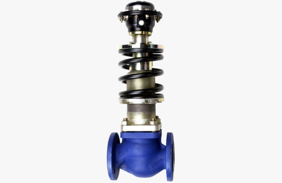
The function of a pressure reducing valve is to lower the system pressure to a predetermined level. A self-acting pressure reducing valve operates by means of an intermediate medium. The desired pressure on the secondary side is selected as the valve’s set pressure.

Pressure reducing valves are suitable for steam, liquids, and gases.

Pressure Reducing Valve Selection

We assist in selecting and sizing a pressure reducing valve that meets the requirements of the application.

Two techniques can be applied for self-acting pressure reduction.

In the first model, a diaphragm-operated disc is installed on top of the valve, to which pressure is applied through an impulse pipe from the valve’s secondary side. In this case, the valve functions based on the pressure coming through the impulse pipe and the spring built into the valve. The spring force, to which the set pressure is adjusted, tends to open the valve when the pressure from the diaphragm device attempts to close it. This operation is found in ARI-Armaturen and GESTRAN pressure reducing valves.

In the second, slightly simpler model, the valve opening is based solely on the spring force built into the valve and its internal structure. This technique is applied in NIEZGODKAN pressure reducing valves.

Steam and Condensate Usage

If it is a steam pressure reduction station, the expansion steam after pressure reduction must be taken into account and the pipe size increased. We are happy to provide guidelines for pipeline sizing and flow rate management.

In large steam pressure reduction stations, a microturbine can be installed alongside the pressure reducing valve, thereby recovering energy from the pressure reduction.

Download Brochures

download

ARI-Armaturen PREDU Pressure Reducing Valves

Lataa PDF
download

ARI-Armaturen PREDU ANSI Pressure Reducing Valves

Lataa PDF
download

ARI-Armaturen PREDU P – Pilot Operated Pressure Reducing Valve

Lataa PDF
download

GESTRA 5801 Self-Acting Pressure Reducing Valves

Lataa PDF
download

Niezgodka Typ 70 Pressure Reducing Valves

Lataa PDF
download

Niezgodka Typ 71 Pressure Reducing Valves

Lataa PDF
download

Niezgodka Typ 74 Pressure Reducing Valves

Lataa PDF

Sludge separators

Sludge separators

Lianerottimet - sludge separators
HEROSE kryogeeninen suodatin - cryogenic filter

Media

Steam and condensate
Cryogenic media
Natural gas, biogas and biomethane
LPG
Process media

Manufacturers

GESTRA
ARI-Armaturen
HEROSE

Technical specifications

Sizes: DN 15-500
Pressure ratings: PN 6-160
Materials: GG-25, GGG 40.3, GS-C 25, AISI 316
Connections: flange, welded, threaded
Other names: mud seal, strainer

What is a sludge separator?

A sludge separator – also called a strainer – is like a filter that ensures that the medium reaches the required degree of purity. Installing a sludge separator is also an easy way to avoid damage and slow the wear of more valuable equipment in the line. Various sludge separator are available with several different mesh sizes.

Sludge separator selection

We assist in selecting the sludge separator that meets the requirements of your application. Our product range covers a wide selection of various sludge separators.

Steel strainers from ARI-Armaturen are suitable for steam and condensate systems. For process systems, strainers can be selected from our acid-resistant models. Additionally, our range includes large basket strainers for high flow rates.

Cryogenic strainers are available from DN 10 to DN 200 and can withstand pressures up to 50 bar in operating temperatures ranging from -196°C to +120°C. Strainers are made of stainless steel and bronze.

Contact our representatives for more information.

Download Brochures

download

ARI-Armaturen Strainers PN6-40 datasheet

Lataa PDF
download

ARI-Armaturen Strainers PN63-160 datasheet

Lataa PDF
download

GESTRA SZ 36A Strainers Datasheet

Lataa PDF

Flanged and welded non-return valves

Flanged and welded non-return valves

laipalliset_ja_hitsattavat_takaiskuventtiilit - Flanged and welded non-return valves
HEROSE-takaiskuventtiili - non-return valve

Media

LPG
Process media
Gas and fuel
Steam and condensate
Cryogenic media
Natural gas, biogas and biomethane

Manufacturers

Edward Flowserve
Tecofi
ARI-Armaturen
HEROSE

Technical Specifications

Sizes: DN 10-500
Pressure Classes: PN 16-500, ASME 150-2500#
Materials: GG-25, GS-C 25, AISI 316, GS-12CrMo19.5
Connection Types: Flanged, welded or between flanges
Other: valves can also be supplied clad
Cryogenic Valves: minimum temperature -196 °C, soft or metal seal, piston, tilting or wafer style check
Other Names: ball check valve, seat check valve, flanged and welded check valves

What are flanged and welded non-return valves?

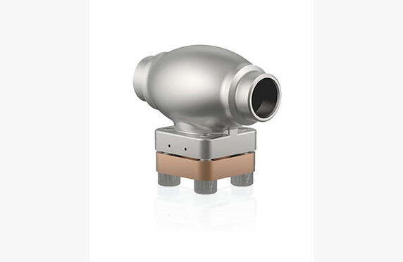
The overall lengths of flanged non-return valves conform to standard dimensions, so replacement of broken valves can be done without pipe modifications. In new installations, it is often more economical to use non-return valves installed between flanges, as they are lighter in construction and more cost-effective.

In waterworks construction, flanged ball non-return valves remain a viable option if the medium contains material that clogs a conventional non-return valve.

Selection of flanged and welded non-return valves

We assist in selecting a non-return valve that meets the requirements of your application. Our sales representatives can provide you with detailed information on the opening characteristics of each valve, as well as support with sizing if needed.

Also, check out our Konwell Academy webinar on selecting and sizing non-return valves.

For steam, condensate, process media, gases, and liquid fuels

In many processes, it is essential to ensure that the non-return valve does not leak from the flange seal. For such applications, welded non-return valves suitable for a variety of materials with pressure classes up to PN 500 are appropriate.

Our product range also covers ASME non-return valves up to a pressure class of 2500#, including those that lock in the open position and sealing non-return valves.

For cryogenic media

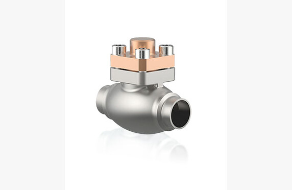
Cryogenic non-return valves require specialized design solutions to meet exceptional cold resistance requirements. Our HEROSEN non-return valves are made from stainless steel and bronze.

Cryogenic non-return valves are available in sizes DN 10-200. They can withstand pressures up to 50 bar at operating temperatures of -196…+120°C. We can size the appropriate non-return valve based on your process data.

Download Brochures

Steam, Condensate, Process Media and Gases

download

Tecofi CBL4240 Flanged Ball Check Valves

Lataa PDF
download

ARI-Armaturen CHECKO-V PN63-160 Check Valves

Lataa PDF
download

ARI-Armaturen CHECKO-V and CHECKO-D Check Valves

Lataa PDF

Liquid Fuels

download

ARI-Armaturen CHECKO-V and CHECKO-D Check Valves

Lataa PDF
download

Tecofi CBL3240 Flanged Ball Check Valves

Lataa PDF

Dual-butterfly non-return valves

Dual-butterfly non-return valves

Media

Gas and fuel
Steam and condensate
Natural gas, biogas and biomethane
LPG
Process media

Manufacturers

GESTRA

Technical specifications

Sizes: DN 50-1200
Pressure Classes: PN 10-40, ASME 150-300#
Body Materials: GG-25, GS-C 25N, AISI 316, 1.0460
Sealing Materials: metal, EPDM, FPM, PTFE, NBR
Connections: Between flanges
Other Names: butterfly check valve, dual-butterfly non-return valve, dual plate check valve

What is a dual-butterfly non-return valve?

Dual-butterfly non-return valves are butterfly valves, which describes their structure very well. In the middle, there is a closing shaft with two symmetrically hemispherical closing plates on either side.

The dual-butterfly non-return valve’s undeniable advantage is its low flow resistance, which depending on the flow is only a few millibars. In other models, it can be a hundred times higher. The valve’s flow resistance can also be adjusted by selecting different springs. The flow resistance depends on the valve’s installation orientation and the springs used. For example, in a vertical pipe when the flow is from bottom to top, the force required to open the valve is greater than, for instance, in a horizontal pipe.

Selecting a dual-butterfly non-return valve

Unlike its competitors, GESTRA uses two separate shafts and each closing plate is secured by two individual closing springs, whereas normally closing springs are not used at all. The robust design is intended to prevent the valve from being damaged by minor hydraulic water shocks. If the system’s water shocks are significant, BB dual-butterfly non-return valves can be equipped with separate hydraulic dampers.

BB dual-butterfly non-return valves are available in various materials.

Our sales representatives can provide you with more detailed information on the opening characteristics of each valve and assist with sizing if needed. They will help you select a dual-butterfly non-return valve that meets the requirements of your application.

Download Brochures

download

GESTRA BB3 C steel, BB3 A stainless steel Dual-Plate Check Valves

Lataa PDF
download

GESTRA BB Dual-Plate Check Valves

Lataa PDF
download

GESTRA BB Dual-Plate Check Valves with Anti-Corrosion Lining

Lataa PDF

Butterfly non-return valves

Butterfly non-return valves

Media

Process media
Gas and fuel
Steam and condensate
Natural gas, biogas and biomethane
LPG

Manufacturers

GESTRA

Technical Specifications

Sizes: DN 50-300
Pressure classes: PN 6-40
Materials: bronze, C22.8, AISI 316
Connection ends: between the discs
Other names: swing check valve, tilting disc check valve

What is a butterfly non-return valve?

Of the non-return valves installed between the discs, the models equipped with a butterfly disc are the simplest in operation. The closing disc is pivoted on one side and the valve is installed with the pivot facing upward. Gravity keeps the disc in the closed position, but it opens when the flow coming from the correct direction reaches the valve. Reverse flow does not open the check valve.

Selection of a butterfly non-return valve

We assist in the selection and sizing of a check valve that meets the requirements of the application.

The butterfly non-return valve is a typical check valve for water systems. The seating retention of GESTRA CB butterfly non-return valves has been reinforced with a separate closing spring, making them extremely robust. In larger sizes than DN 100, the flow resistance is clearly lower than with the GESTRA RK model. However, if low flow resistance is a procurement criterion, the flow resistance in the butterfly non-return valve remains significantly higher than in the double-disc check valve.

Damped Water Hammers

Backflowing liquid can cause a high closing force/pressure that the valve components cannot withstand. It is quite typical that from sizes DN 500 upward, a closing damping is used. Damping can also be used in smaller sizes.

Damping can be done hydraulically, where damping pistons directly slow the disc movement. Another method is using a gear (mechanical/hydraulic). In this case, the disc’s lever is connected to the lever of a hydraulic cylinder. Both have a gear that dampens the closing force.

With gear-equipped damping, a higher duration of closing pressure can be achieved than with purely hydraulically damped valves. It is important to determine the closing pressure in a failure situation. For example, when the pump stops, the pressure of the back-flowing water should be determined before sending out a request for quotation. Damped check valves are typically of the tilting disc (tilting disc check valve) or double-disc type.  

Download Brochures

download

GESTRA CB24S, CB26, CB26A Swing Check Valves

Lataa PDF
download

GESTRA CB14 Swing Check Valves

Lataa PDF

Disco and lined non-return valves

Disco and lined non-return valves

Media

Gas and fuel
Steam and condensate
Natural gas, biogas and biomethane
LPG
Process media

Manufacturers

GESTRA
ChemValve

Technical specifications

Sizes: DN 15-200
Pressure classes: PN 10-160, ASME 150-900#
Materials: GG-25, GS-C 25 N, AISI 316, special brass, hastelloy
Connection ends: between flanges, threaded
Other names: flange check valve, disco check valve, lined non-return valve

What are Disco and lined non-return valves?

DISCO check valves are compact axial type valves, in which the closure spring is symmetrically located in the center of the valve.

DISCO-style check valves are best suited primarily for smaller pipes, as their flow resistance compared to other check valves installed between flanges increases with larger pipe sizes.

Selection of disco and lined non-return valves

There are several materials available for the body, disc, and spring, making it possible to create customized solutions such as choosing a hastelloy spring while the other parts are made of acid-resistant steel. The standard opening pressure is 5 mbar. Other spring forces can be selected from an extensive range up to 3000 mbar.

Soft seals are also available in EPDM, FPM, NBR or PTFE.

MB is a threaded brass check valve for water systems. All RK models are installed between flanges. Depending on the model, the body materials include special brass, various grades of stainless steel, or acid-resistant steel.

The range also includes PN 160 high pressure valves.

We assist in selecting and sizing the check valve that meets the requirements of the application.

Download Brochures

Steam, condensate and liquid fuels

download

GESTRA RK86, RK86A, RKE86, RKE86A Non-Return Valve for Sandwiching Between Flanges

Lataa PDF
download

GESTRA RK76 Non-Return Valves for Sandwiching Between Flanges

Lataa PDF
download

GESTRA RK70, RK71 Non-Return Valves

Lataa PDF
download

GESTRA RK44 Non-Return Valves for Sandwiching Between Flanges

Lataa PDF
download

GESTRA RK41 Non-Return Valves for Sandwiching Between Flanges

Lataa PDF
download

GESTRA MB14 Non-Return Valves

Lataa PDF

Process fluids

download

AZ-Armaturen Delta and Globus Ball Check Valves with Lining

Lataa PDF
download

GESTRA RK86, RK86A, RKE86, RKE86A Non-Return Valve for Sandwiching Between Flanges

Lataa PDF
download

GESTRA RK76 Non-Return Valves for Sandwiching Between Flanges

Lataa PDF
download

GESTRA RK70, RK71 Non-Return Valves

Lataa PDF
download

GESTRA RK44 Non-Return Valves for Sandwiching Between Flanges

Lataa PDF
download

GESTRA RK41 Non-Return Valves for Sandwiching Between Flanges

Lataa PDF
download

GESTRA MB14 Non-Return Valves

Lataa PDF
download

ChemValve DTEF Non-Return Valves

Lataa PDF

Burner equipment

Burner equipment

Media

Natural gas, biogas and biomethane
LPG

Manufacturers

Other manufacturers

Technical specifications

Included devices: pressure regulators, pressure switches, motorized valves, solenoid valves, burner controls, pilot controls, multiblocks, leak testers
Other names: gas burner equipment

What are burner equipment?

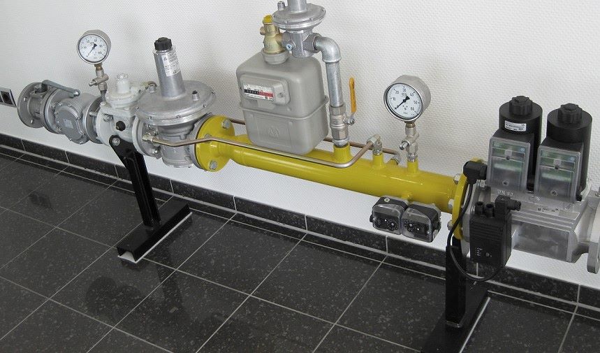
Burner equipment include various devices that control the supply of gas and combustion air to the burner. This includes, among others, pressure regulators, pressure switches, solenoid valves, and burner controls.

Selection of burner equipment

Our product range typically includes the burner valve group devices used in Finland from both Dungs and Kromschröder. The full product range is available from both, which naturally includes much more than just burner valve groups. For example, Kromschröder’s VK series quick closure motorized valves and pilot burners.

The Kromschröder product range:

  • VGBF and GDJ pressure regulators
  • DG pressure switches
  • VK motorized valves
  • VAS and VCS solenoid valves
  • BCU, IFS and IFD burner controls
  • ZAI pilot burners

The Dungs product range:

  • FR pressure regulators
  • GW and LGW pressure switches
  • DMV solenoid valves
  • MB multiblocks
  • VDK and VPS leak testers

In addition, we supply a comprehensive range of spare parts for burners from various manufacturers.

We assist in selecting burner equipment that meet the requirements of your application. Ask our contacts for more information.

Gas blowers

Gas blowers

Mapro gas blower - kaasupuhallin
Teollisuuden kaasupuhaltimet

Media

Natural gas, biogas and biomethane

Manufacturers

MAPRO

Technical Specifications

Other names: pressure booster blower, gas blower

What is a gas blower?

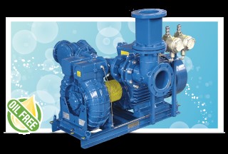
Pressure boosting blowers are suitable for increasing the pressure of natural gas and biogas, for example at biogas plants or natural gas pipelines, where it is necessary to transfer low-pressure gas from one place to another.

Choosing a gas blower

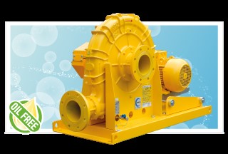
Mapro International is a traditional and well-known Italian blower manufacturer. They offer a wide range of different blowers for air and combustible gases. Mapro also has its own product line of blowers suitable for biogas, and Mapro’s blowers are widely used in biogas plants. All blowers naturally comply with European standards and, if necessary, are ATEX classified.

We help you select the appropriate flame detector according to the requirements of the application. Ask our contact persons for more information.

Gas leak detection and alarm systems

Gas leak detection and alarm systems

Media

Natural gas, biogas and biomethane
LPG

Manufacturers

GWS Gaswarngeräte

Technical Specifications

Other names: gas leak alarm system, gas warning system

What is a gas alarm system?

A gas alarm system – also known as a gas leak alarm system – provides safety for all gas users. In premises where gas is used or stored, a functioning gas leak alarm system is required by law and regulations. The same applies to premises through which gas pipelines run. The gas alarm system is an important part of the equipment ensemble that makes your gas system safe and reliable under all conditions.

Choosing a Gas Alarm System

Our range includes high-quality gas detectors and alarm systems from German GWS. GWS alarm systems can be equipped, if necessary – for example, based on the size of the premises – with an appropriate number of sensors as well as the desired number of sirens and warning lights. The alarm can also be forwarded to a process control system or another similar information system.

We also supply alarm systems to monitor systems other than land and liquefied petroleum gas systems. For example, processes that involve the use of oxygen or where carbon monoxide or some other harmful gas may accumulate are very typical targets for alarm systems.

We assist in selecting a gas alarm system that meets the requirements of the application. Contact our representatives for more information.