Dual-butterfly non-return valves

Dual-butterfly non-return valves

Media

Steam and condensate
Natural gas, biogas and biomethane
LPG
Process media
Gas and fuel

Manufacturers

GESTRA

Technical specifications

Sizes: DN 50-1200
Pressure Classes: PN 10-40, ASME 150-300#
Body Materials: GG-25, GS-C 25N, AISI 316, 1.0460
Sealing Materials: metal, EPDM, FPM, PTFE, NBR
Connections: Between flanges
Other Names: butterfly check valve, dual-butterfly non-return valve, dual plate check valve

What is a dual-butterfly non-return valve?

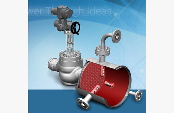
Dual-butterfly non-return valves are butterfly valves, which describes their structure very well. In the middle, there is a closing shaft with two symmetrically hemispherical closing plates on either side.

The dual-butterfly non-return valve’s undeniable advantage is its low flow resistance, which depending on the flow is only a few millibars. In other models, it can be a hundred times higher. The valve’s flow resistance can also be adjusted by selecting different springs. The flow resistance depends on the valve’s installation orientation and the springs used. For example, in a vertical pipe when the flow is from bottom to top, the force required to open the valve is greater than, for instance, in a horizontal pipe.

Selecting a dual-butterfly non-return valve

Unlike its competitors, GESTRA uses two separate shafts and each closing plate is secured by two individual closing springs, whereas normally closing springs are not used at all. The robust design is intended to prevent the valve from being damaged by minor hydraulic water shocks. If the system’s water shocks are significant, BB dual-butterfly non-return valves can be equipped with separate hydraulic dampers.

BB dual-butterfly non-return valves are available in various materials.

Our sales representatives can provide you with more detailed information on the opening characteristics of each valve and assist with sizing if needed. They will help you select a dual-butterfly non-return valve that meets the requirements of your application.

Download Brochures

download

GESTRA BB3 C steel, BB3 A stainless steel Dual-Plate Check Valves

Lataa PDF
download

GESTRA BB Dual-Plate Check Valves

Lataa PDF
download

GESTRA BB Dual-Plate Check Valves with Anti-Corrosion Lining

Lataa PDF

Butterfly non-return valves

Butterfly non-return valves

Media

Steam and condensate
Natural gas, biogas and biomethane
LPG
Process media
Gas and fuel

Manufacturers

GESTRA

Technical Specifications

Sizes: DN 50-300
Pressure classes: PN 6-40
Materials: bronze, C22.8, AISI 316
Connection ends: between the discs
Other names: swing check valve, tilting disc check valve

What is a butterfly non-return valve?

Of the non-return valves installed between the discs, the models equipped with a butterfly disc are the simplest in operation. The closing disc is pivoted on one side and the valve is installed with the pivot facing upward. Gravity keeps the disc in the closed position, but it opens when the flow coming from the correct direction reaches the valve. Reverse flow does not open the check valve.

Selection of a butterfly non-return valve

We assist in the selection and sizing of a check valve that meets the requirements of the application.

The butterfly non-return valve is a typical check valve for water systems. The seating retention of GESTRA CB butterfly non-return valves has been reinforced with a separate closing spring, making them extremely robust. In larger sizes than DN 100, the flow resistance is clearly lower than with the GESTRA RK model. However, if low flow resistance is a procurement criterion, the flow resistance in the butterfly non-return valve remains significantly higher than in the double-disc check valve.

Damped Water Hammers

Backflowing liquid can cause a high closing force/pressure that the valve components cannot withstand. It is quite typical that from sizes DN 500 upward, a closing damping is used. Damping can also be used in smaller sizes.

Damping can be done hydraulically, where damping pistons directly slow the disc movement. Another method is using a gear (mechanical/hydraulic). In this case, the disc’s lever is connected to the lever of a hydraulic cylinder. Both have a gear that dampens the closing force.

With gear-equipped damping, a higher duration of closing pressure can be achieved than with purely hydraulically damped valves. It is important to determine the closing pressure in a failure situation. For example, when the pump stops, the pressure of the back-flowing water should be determined before sending out a request for quotation. Damped check valves are typically of the tilting disc (tilting disc check valve) or double-disc type.  

Download Brochures

download

GESTRA CB24S, CB26, CB26A Swing Check Valves

Lataa PDF
download

GESTRA CB14 Swing Check Valves

Lataa PDF

Disco and lined non-return valves

Disco and lined non-return valves

Media

Steam and condensate
Natural gas, biogas and biomethane
LPG
Process media
Gas and fuel

Manufacturers

ChemValve
GESTRA

Technical specifications

Sizes: DN 15-200
Pressure classes: PN 10-160, ASME 150-900#
Materials: GG-25, GS-C 25 N, AISI 316, special brass, hastelloy
Connection ends: between flanges, threaded
Other names: flange check valve, disco check valve, lined non-return valve

What are Disco and lined non-return valves?

DISCO check valves are compact axial type valves, in which the closure spring is symmetrically located in the center of the valve.

DISCO-style check valves are best suited primarily for smaller pipes, as their flow resistance compared to other check valves installed between flanges increases with larger pipe sizes.

Selection of disco and lined non-return valves

There are several materials available for the body, disc, and spring, making it possible to create customized solutions such as choosing a hastelloy spring while the other parts are made of acid-resistant steel. The standard opening pressure is 5 mbar. Other spring forces can be selected from an extensive range up to 3000 mbar.

Soft seals are also available in EPDM, FPM, NBR or PTFE.

MB is a threaded brass check valve for water systems. All RK models are installed between flanges. Depending on the model, the body materials include special brass, various grades of stainless steel, or acid-resistant steel.

The range also includes PN 160 high pressure valves.

We assist in selecting and sizing the check valve that meets the requirements of the application.

Download Brochures

Steam, condensate and liquid fuels

download

GESTRA RK86, RK86A, RKE86, RKE86A Non-Return Valve for Sandwiching Between Flanges

Lataa PDF
download

GESTRA RK76 Non-Return Valves for Sandwiching Between Flanges

Lataa PDF
download

GESTRA RK70, RK71 Non-Return Valves

Lataa PDF
download

GESTRA RK44 Non-Return Valves for Sandwiching Between Flanges

Lataa PDF
download

GESTRA RK41 Non-Return Valves for Sandwiching Between Flanges

Lataa PDF
download

GESTRA MB14 Non-Return Valves

Lataa PDF

Process fluids

download

AZ-Armaturen Delta and Globus Ball Check Valves with Lining

Lataa PDF
download

GESTRA RK86, RK86A, RKE86, RKE86A Non-Return Valve for Sandwiching Between Flanges

Lataa PDF
download

GESTRA RK76 Non-Return Valves for Sandwiching Between Flanges

Lataa PDF
download

GESTRA RK70, RK71 Non-Return Valves

Lataa PDF
download

GESTRA RK44 Non-Return Valves for Sandwiching Between Flanges

Lataa PDF
download

GESTRA RK41 Non-Return Valves for Sandwiching Between Flanges

Lataa PDF
download

GESTRA MB14 Non-Return Valves

Lataa PDF
download

ChemValve DTEF Non-Return Valves

Lataa PDF

Steam generators

Steam generators

Media

Steam and condensate

Manufacturers

GESTRA
Other manufacturers

Technical specifications

Other: custom manufactured
Other names: clean steam generators, saturated steam generators

What is a steam generator?

Steam generators can be used to produce steam for, for example, sterile clean-steam applications as well as for more conventional processes.

Choosing a steam generator

We help you select a steam generator that meets the requirements of your application. Ask our contacts for more information.

Clean steam generators

Clean steam generators are used when clean saturated steam is required. Applications include, among others, hospitals and the food industry.

A clean steam generator produces saturated steam from treated water, which contains neither oxygen nor impurities. Steam can be produced either with “dirty” steam or electrically.

Konwell supplies clean steam generators customized to the customer’s needs. The generators include a feed water tank, oxygen removal, and water pre-heating.

Saturated steam generators

Saturated steam generators are used when the steam demand and pressure are low. The licensing requirements are also lighter than for steam boilers. Applications include, among others, laundries, the textile industry, and the construction industry.

Steam is produced in the generator by a burner or electrically.

Konwell also supplies electric steam generators.

Steam desuperheating

Steam desuperheating

hoyrynmuuntoasemat - steam conditioning stations
ldm hoyrynmuuntoasema - steam conditioning station
ldm_reduktio

Media

Steam and condensate

Manufacturers

SART von Rohr
LDM

Technical Specifications

Direct spraying into seat
Sizes: DN 40-250, water connection DN 15-40
Pressure classes: PN 16-100
Materials: GS-C 25, GS-17CrMO55
Connection types: flanged
Other: various nozzle options depending on the application

Spraying to expanded outlet
Sizes: steam connection DN 25-400
Pressure classes: PN 40-600
Materials: GS-C 25, GS-17CRMO55, 13CrMo44, 10CrMo910
Connection types: flanged, welded
Other: various nozzle options depending on the application, cooling nozzle available with steam dispersant

Other names: steam-conditioning station

What is Steam Desuperheating?

In power plant processes, steam is usually produced in a superheated state so that it does not condense unnecessarily in the transfer pipeline but remains as steam.

However, the heat transfer capacity of superheated steam is inferior compared to that of saturated steam, and therefore it must be cooled to a temperature close to that corresponding to the pressure of saturated steam. This can be done using a separate valve.

Selection of Equipment

Precision determines the cooling method chosen.

Cooling of superheated steam is most commonly done by controlled injection of cooling water into the steam. The cooling water is sprayed either directly into the valve seat or immediately after the valve. The operation is relatively simple and failsafe. By adding cooling water, the temperature can at best be brought to +3 °C relative to that of saturated steam.

Often, the valve is equipped with a separate expansion chamber, which is placed immediately afterwards. It allows for the expansion of the steam under lower pressure. The expansion chamber extends the lifespan of the valve and helps in controlling noise levels.

Depending on the required accuracy of cooling and the amount of water, cooling water is directed to the expansion section using various techniques. It can be atomized into the steam as water vapor or the steam can be driven through a water sheet. If necessary, perforated plates/silencers can be added to the expansion section to reduce the flow rate in a controlled manner to lower noise levels.

If the process requires fully saturated steam, it can be produced using a separate steam desuperheating machine.

We assist in selecting the equipment used for desuperheating according to the application’s requirements. Ask our contact persons for more information.

Download Brochures

download

LDM 700 line control valves and steam-conditioning stations

Lataa PDF
download

LDM 900 line control valves and steam-conditioning station in angle way execution

Lataa PDF
download

LDM CHPR Desuperheater

Lataa PDF
download

LDM Injection Head Drive-Steam Type VHP

Lataa PDF
download

LDM Injection head mechanical VH

Lataa PDF
download

SART von Rohr BYVAP Steam desuperheater Type DMBC

Lataa PDF
download

SART von Rohr BYVAP Steam desuperheater Type DVX

Lataa PDF

Limit switches

Limit switches

Venttiilien rajakytkimet - valve limit switches
TU-B-II-Toimil-4_Fema limit switch

Media

Cryogenic media
Natural gas, biogas and biomethane
LPG
Process media
Gas and fuel
Steam and condensate

Manufacturers

Emme Technology (Max-Air)
Netherlocks
Rotork
Sofis

Technical specifications

Other names: valve limit switch, valve position indicator, signal box

What is a valve limit switch?

Using limit switches, the system can easily and reliably obtain, for example, valve open/close status data, which can be further transmitted electronically to the control system.

In mechanical models, a switch is installed on the valve yoke that opens or closes with the movement of the valve. In this way, information on whether the valve is open or closed is obtained.

The inductive switch sends a trigger signal when metal or another electrically conductive material approaches the sensing surface.

The operation of the magnetic switch is based on changes in the magnetic field when the valve yoke rises or falls.

Limit Switch Selection

Our program includes mechanical, inductive, and magnetic limit switches. We assist in selecting the limit switch that meets the application’s requirements, including for ATEX zones.

Netherlocks, part of the Sofis group, manufactures compact VPI open/closed limit packages, which can be installed on virtually any existing valve. Both on rotary-operating valves and on manually operated screw valves. Our installation service measures the necessary dimensions from the existing valve for the intermediary parts. After delivery, we proceed to install and set up the limit package.

Contact our representatives for more information.

Download Brochures

download

Max-Air BE41-BS42 Limit Switch Box

Lataa PDF
download

Max-Air BE45 SERIES Box Micro Limit Switch Box

Lataa PDF
download

Max-Air BE48 BS48 BM48 Ex Limit Swiches datasheet

Lataa PDF
download

Sofis VPI Position Indicator

Lataa PDF
download

Netherlocks VPI Position Indicator

Lataa PDF
download

Rotork Limit Switch Boxes

Lataa PDF

Valve positioners

Valve positioners

Media

Steam and condensate
Cryogenic media
Natural gas, biogas and biomethane
LPG
Process media
Gas and fuel

Manufacturers

Siemens
ARI-Armaturen

Technical specifications

Other names: valve positioner

What is a valve positioner?

The valve positioner usually converts a 4…20 mA current signal either into a proportional pneumatic output signal for a pneumatic actuator or drives a motor actuator in steps in the desired direction.

It is also possible to use a 0/2…10 V voltage signal or various digital fieldbus signals, such as Profibus, Fieldbus Foundation, or ASI, as a control signal.

Choosing a valve positioner

The SIPART PS2 digital valve positioner can be used in both linear and rotary pneumatic actuators, both single- and dual-acting. There is an option for the HART communication protocol, which allows for diagnosing the valve and tuning it using a programming device.

Digital and electro-pneumatic positioners from other manufacturers are also available according to customer needs.

We assist in selecting the appropriate positioner according to the requirements of the application. Ask our contacts for more information.

Download brochures

download

ARI-Armaturen STEVI-POS positioner

Lataa PDF
download

Siemens Sipart PS2 Positioners datasheet

Lataa PDF

Electric actuators

Electric actuators

ARI-Armaturen PREMIO electric actuator - sähköinen toimilaite
Electric actuators
Toimilaitteelliset_kiilaluistiventtiilit
kiilaluistiventtiili sahkoisellä toimilaitteella

Media

Steam and condensate
Cryogenic media
Natural gas, biogas and biomethane
LPG
Process media
Gas and fuel

Manufacturers

BERNARD CONTROLS
ARI-Armaturen
Rotork
AUMA

Technical Specifications

Other names: motor actuator, electric actuator

What is an Electric Actuator?

Shut-off and regulating valves can be equipped with an actuator, allowing the valve to be controlled from a location other than in its immediate vicinity. Whereas pneumatic actuators use compressed air to operate, electric actuators use electricity.

In large actuators, short-circuit motors (synchronous motor) have traditionally been used, in which the valve is directed in the desired direction by changing the polarity of the rotor windings with alternating current. Actuators are supplied only for a specific voltage and frequency.

Brushless DC motors (BLDC) have become common in smaller actuators, enabling the use of 24 VDC as well as providing flexibility with AC voltages. For example, as standard, the ARI-Premio-Plus actuator operates within a voltage range of 90–264 VAC, 47–63 Hz.

The advantage of electric actuators is their significantly greater force output relative to their size compared to pneumatic actuators. Therefore, they are well suited for large, high-force valves such as wedge gate valves.

Selection of an Electric Actuator

We assist in selecting an electric actuator that meets the requirements of your application.

Our product portfolio includes ARI PREMIO electric linear actuators, whose power capacity is designed in a sensible and cost-effective manner for ARI shut-off and control valves. We also offer other electric actuators available on the market, such as AUMA, Bernard, and Rotork.

In our recorded webinar, we presented ARI-Armaturen’s PREMIO-PLUS 2G actuator.

Contact our representatives for more information about electric actuators.

Download Brochures

download

ARI-Armaturen ARI-PREMIO

Lataa PDF
download

ARI-Armaturen ARI-PREMIO-Plus 2G

Lataa PDF
download

ARI-PREMIO FAIL SAFE Electric Actuator with safety reset Datasheet

Lataa PDF
download

ARI-Armaturen FR1.2_Electric Thrust Actuator Datasheet

Lataa PDF
download

ARI-Armaturen FR2.1-2.2 Electric Thrust Actuator Datasheet

Lataa PDF
download

ARI-Armaturen ARI-OM

Lataa PDF

Pneumatic actuators

Pneumatic actuators

ARI-Armaturen DP pneumatic actuator - pneumaattinen toimilaite
TU-B-II-Valve Actuator Fema
ALFA Pneumaattiset_toimilaitteet
TU-B-II Fema actuator - toimilaite
HEROSE toimilaitteellinen sulkuventtiili

Media

Cryogenic media
Natural gas, biogas and biomethane
LPG
Process media
Gas and fuel
Steam and condensate

Manufacturers

Rotork
SART von Rohr
ARI-Armaturen

Technical Specifications

Others: suitable for both linear and rotary movements
Other names: diaphragm actuator, pneumatic actuator, rack and pinion actuator, scotch-yoke actuator

What is a pneumatic actuator?

A shut-off valve can be equipped with an actuator, allowing the valve to be controlled from a location other than its immediate vicinity. In pneumatic actuators, compressed air controls the actuator to open or close.

In dual-action actuators, compressed air both opens and closes the valve.

In single-action models, the operation can be designed so that compressed air either opens or closes the valve, and an internal spring within the actuator performs the opposite movement if the compressed air is lost.

The advantages of a pneumatic actuator include its quick response and resistance to vibration compared to electric actuators.

Selecting a Pneumatic Actuator

Pneumatic actuators are divided into rotary actuators (90º / 120º) – which are suitable for ball, butterfly, and plug valves – and linear actuators, which are suitable for sleeve and slide valves.

Our stock of rotary actuators includes GT (gear) and RC (scotch-yoke) single- and dual-action pneumatic actuators. Upon request, we also equip valves with actuators from other brands.

In ARI-Armaturen sleeve valves, we use the factory’s own linear DP actuators.

Pneumatic actuators can be equipped with various limit packages, positioners, and solenoid valves.

We assist in selecting the pneumatic actuator that meets the requirements of your application. Contact our representatives for more information.

Download Brochures

download

Rotork GT-Range Pneumatic Actuators Datasheet

Lataa PDF
download

Rotork RC200 Range

Lataa PDF
download

ARI-Armaturen DP30-35 Pneumatic Actuators

Lataa PDF

Level switches

Level switches

Pintakytkin - level switch KSR 9454
säiliön pintakytkimet - tank level switch
Pintakytkin_NRGS_9975
NRGS16-1_001_LR1

Media

Steam and condensate
Cryogenic media
LPG
Process media
Gas and fuel

Manufacturers

GESTRA
Aplisens
Intra-Automation

Technical specifications

Other designations: level switch

What is a level switch?

Level switches transmit information to the system when the liquid reaches a predetermined height. The system then controls the process based on this information.

Level switch selection

We assist in selecting a level switch that meets the requirements of the application. Contact our representatives for more information.

Our range includes float switches that can be installed from the top or from the sides. The float switch is a traditional and quite cost-effective method for performing an on-off level measurement. Vertical models are available with several limit switches.

A somewhat more modern method is electrode measurement. Its advantage is that it is maintenance‐free, as the electrode does not have any so-called moving parts. Electrodes are clearly suitable for higher temperatures than float switches, making them applicable, for example, in steam boilers.

If limit switches are sufficient for level control, the best solution is the GESTRA conductive electrode, which can provide up to four separate limit signals. A compact model is also available, in which four separate voltage-free changeover contacts are integrated into the electrode.

Conductive level switches based on conductivity measure the resistance when immersed in the liquid. They are used for conductive liquids. Applications include dry run protection, prevention of overfilling, and on-off level control.

Limit switches are also available for magnetically controlled level indicators, providing limit data in addition to a local display.

Download brochures

download

Aplisens Type ERH Level Switch datasheet

Lataa PDF
download

Intra-Automation Magnetically Controlled Liquid Level Indicator Type ITA

Lataa PDF
download

Intra-Automation ITA Magnetic Sensing Transmitter

Lataa PDF
download

Intra-Automation ITA Magnetic Multi-Float-Switch

Lataa PDF
download

GESTRA NRGS11-2 NRGS16-2 Level Monitoring Datasheet

Lataa PDF
download

GESTRA NRGS11-1 NRGS16-1 NRGS16-1S Level Monotoring Datasheet

Lataa PDF
download

WIKA Float Switch HSL-S HLS-P Datasheet

Lataa PDF
download

WIKA Float Switch FLS-S FLS-M FLS-P FLS-H

Lataa PDF