Condensate lifters

Condensate lifters

GESTRA FPS14-011 lauhteennostin - Condensate lifter
fps_rakennekuva
una25_lauhteennostin
kh_rakennekuva

Media

Steam and condensate

Manufacturers

ARI-Armaturen
GESTRA

Technical specifications

Details: customized according to the pumping capacity
Other: also for Atex areas
Other names: condensate lifter

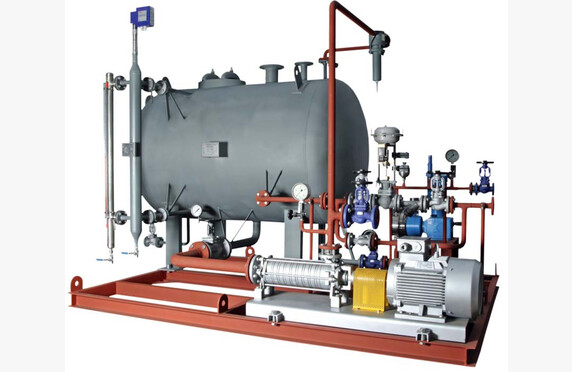
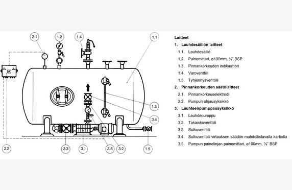
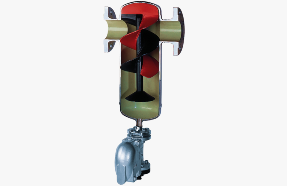
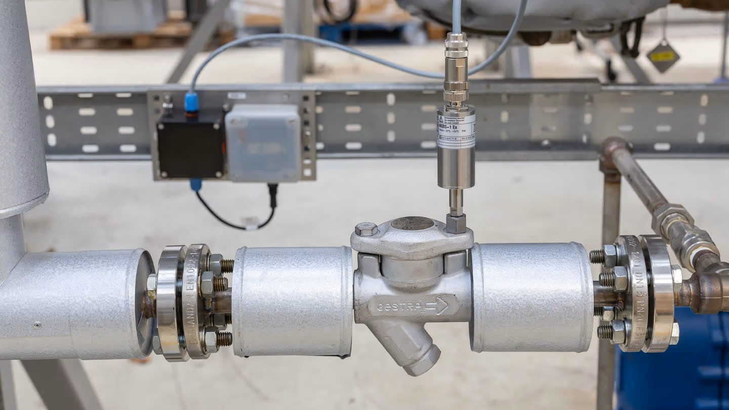
What is a condensate lifter?

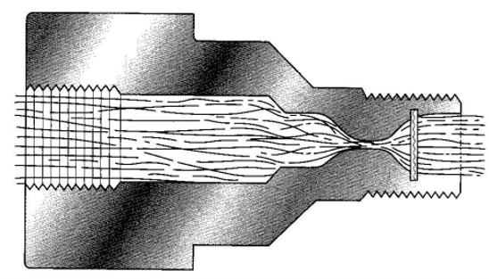
Condensate systems should in principle always be designed to be downward flowing. However, this is not always possible, and during condensate removal the condensate must sometimes be lifted upward. A rising condensate line is not inherently a problem as long as the line has sufficient pressure to overcome the condensate system pressure combined with hydrostatic back pressure. Problems typically arise in situations where the system’s inlet pressure drops, for example, when a control valve closes. In such cases, the pipeline remains waterlogged, inevitably leading to water hammer in the system. As its name implies, the condensate lifter helps to lift condensate in rising condensate lines.

Choosing the condensate lifter

We help you choose the appropriate model based on application and capacity.

GESTRA offers several solutions for lifting condensate, and the choice among them is based, among other factors, on the amount of condensate as well as the desired lifting height.

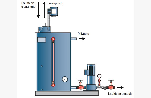
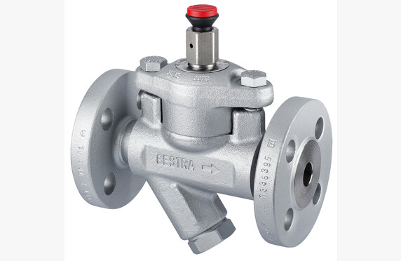
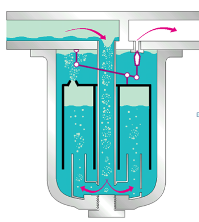
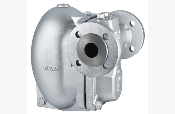
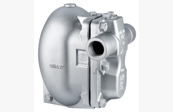
If the amount of condensate and lifting height are relatively small, excellent alternatives are the self-priming ED condensate lifter or the compact steam-assisted condensate lifter combination UNA 25-PS. Alternatively, a condensate removal/condensate lifter combination UNA 25-PK could be used, in which case a separate condensate remover is not required.

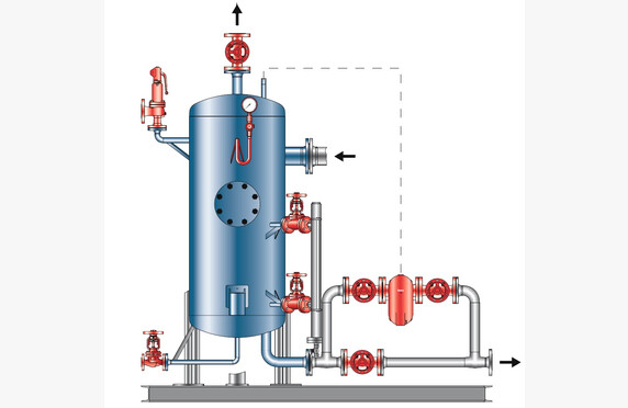
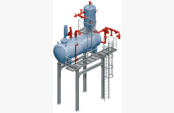
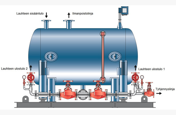
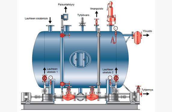
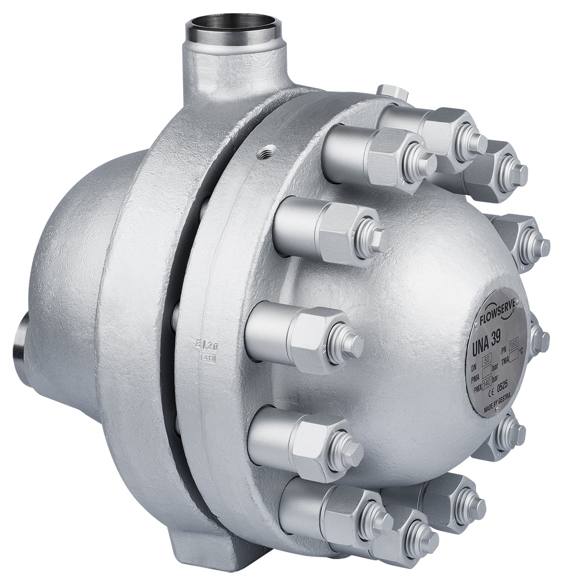
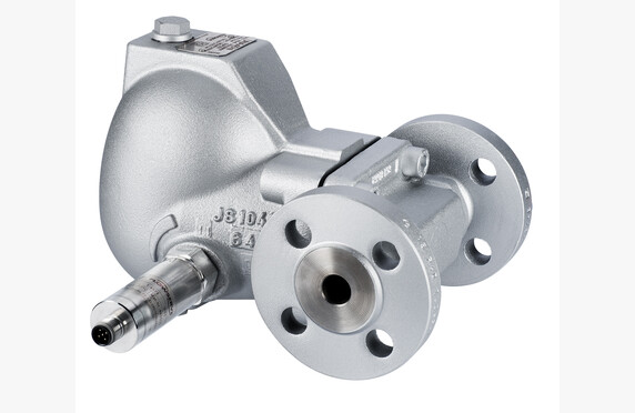
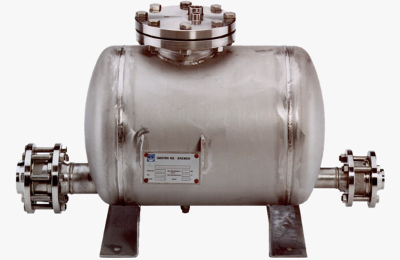
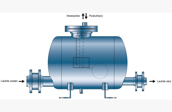
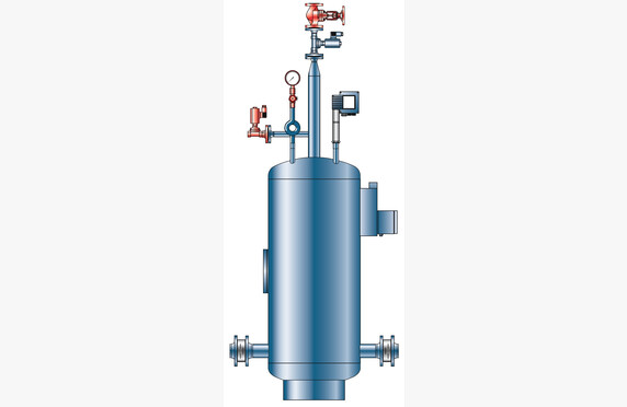
When the amount of condensate is larger, we recommend the steam-assisted self-priming FPS or KH condensate lifter. The FPS condensate lifter operates based on buoyancy technology and is also suitable for Atex areas. In contrast, the KH operates based on sensor technology and its capacity is essentially unlimited.

Download Brochures

download

GESTRA UNA25-PK Pump Trap, UNA25-PS Condensate Lifter

Lataa PDF
download

GESTRA FPS23 Steam-Powered Condensate-Return Unit

Lataa PDF
download

GESTRA KH Steam-Powered Condensate-Return Unit

Lataa PDF
download

GESTRA ED Condensate Dampening Pot

Lataa PDF
download

GESTRA FPS14 Steam-Powered Condensate-Return Uni

Lataa PDF
download

ARI-Armaturen CONLIFT Float-operated condensate pump

Lataa PDF

Flash vessel

Flash vessel

VD_paisuntahoyryjarjestelma - flash vessel
VD_paisuntahoyryjarjestelma_varikuva

Media

Steam and condensate

Manufacturers

GESTRA

Technical specifications

Other names: expansion steam tank, flash vessels for condensate recovery

What is a flash vessel?

An expansion steam vessel is designed for all applications where, for example, expansion steam is generated from condensate, boiler blowdown, or hot water. The expansion steam vessel can, for example, capture the heat from the boiler blowdown.

Selection of a flash vessel

We help in selecting the expansion steam vessel that meets the application requirements. Ask our contacts for more information.

GESTRA VD flash vessel

The device consists of an expansion steam vessel, condensate inlet, expansion steam outlet, and condensate outlet connections, as well as several safety and control device connections. GESTRA VD expansion steam vessels are particularly suitable for heat recovery purposes from boiler blowdown. The device is designed and sized according to the operating parameters of the system.

Condensate flows into the vessel through the inlet connection on the side. Thanks to the installation position of the inlet connection, the expansion steam vessel functions like a cyclone separator, forcing the incoming condensate to flow in a spiral within the vessel. The centrifugal force separates expansion steam from the condensate, with a residual moisture content of less than 1 %. Additionally, the rotational effect reduces erosive impacts from the flow, which otherwise would wear out the system components.

The lower part of the vessel is designed so that the condensate being directed to the condensate drain is free of vapor bubbles. VD expansion steam vessels are sized for an operating pressure of 12 bar and maximum temperatures of 200 °C.

The condensate level in the vessel can be visually monitored using an optional magnetic liquid level gauge. If necessary, an optional bypass for the condensate drain can also be installed. The vessel has a separate inspection opening for examining the interior of the vessel.

Pump-driven or electric/electropneumatic condensate drainage systems are available on separate request.

GESTRA VD23/26 flash vessel

VD23 and VD26 expansion steam vessels, together with UNA turbine condensate drains, form a compact expansion steam system. The vessels feature connections for condensate inlet as well as outlets for expansion steam and condensate. The purpose is the separation of expansion steam from the condensate. The vessels are available in both vertical and horizontal models. All expansion steam vessels are sized according to process values.

Condensate is directed into the vessel through a protective plate, whose function is to reduce erosive impacts on the equipment caused by the condensate. The structure of the lower part of the condensate vessel ensures that the condensate is free of vapor bubbles when reaching the condensate drain.

Download brochures

download

GESTRA Flash Vessel VD DBL 818997 01

Lataa PDF

Feedwater tank and deaeration

Feedwater tank and deaeration

NDR-SW_kaasunpoistin_ja_lauhdesailio_varikuva
NDR_kaasunpoistin_vari-toimintakuva
SW_lauhdesailio_piirroskuva

Media

Steam and condensate

Manufacturers

GESTRA
Konwell

Technical specifications

Others: manufactured custom-tailored
Other names: feedwater tank, deaeration dome

What is Feedwater Deaeration?

The feedwater deaeration system consists of a feedwater tank and an air removal plenum. The purpose of the device is to remove non-condensable gases dissolved in the process medium, such as oxygen and carbon dioxide.

The boiler water must be free from scaling components to prevent scale formation on the heating surfaces. The presence of undissolved oxygen or carbon dioxide causes severe corrosion damage to the boiler’s heating surfaces. The feedwater deaeration system is always designed according to the customer’s needs and process requirements, and it meets the general thermodynamic requirements for optimal performance.

To achieve optimal deaeration, make-up water and return condensate are directed into a compartmentalized air removal plenum to maximize liquid splashing. The heating steam is introduced into the air removal plenum from below. After deaeration, the make-up water and condensate flow directly into the feedwater tank connected by a flange to the deaerator. The feedwater is heated in the tank using steam nozzles up to 107 °C.

The solubility of gases in water is described by “Henry’s Law”, according to which the solubility decreases when the partial pressure of the gas above the solution decreases. In practice, this means that the solubility of gases in water diminishes as the temperature rises and approaches the saturation temperature.

In the deaerator, the make-up water and return condensate are divided into several compartments where they are in direct contact with the heating steam. This process reduces the solubility of oxygen and carbon dioxide and removes them from the feedwater. The released gases rise to the top of the tank, from where they are directed through the air removal plenum into the ventilation system.

For maintaining the water temperature in the feedwater tank, we recommend using a temperature-controlled valve, and for maintaining the gas space pressure, a pressure-controlled valve. With liquid process fluids, it is important to determine the pump’s available suction head (NPSH, Net Positive Suction Head) to prevent cavitation. The pressure of the liquid inside the pump must always remain above the prevailing boiling point. NPSH is pump-dependent.

Installation of the system reduces the water oxygen content by 0.02 mg/l.

Selection of Feedwater Tank and Deaeration System

We assist in selecting the solution that meets the requirements of your application. Contact our representatives for more information.

Download Brochures

download

GESTRA Feedwater Deaerating Plant Deaerating Dome NDR and Feedwater Tank SW

Lataa PDF

Automated condensate return unit

Automated condensate recovery unit

SDI Lauhteenpalautussäiliö - automated condensate recovery unit
SDL-SDS-mp_lauhteenpalautusyksikko_varikuva
SDL_SDS_hp-lauhteenpalautusyksikko_varikuva
SDR_lauhteenpalautusyksikko_varikuva
SDI_Lauhteenpalautusyksikko_osaluettelolla
SDI_Lauhteenpalautusyksikko_piirroskuva
SDI_Lauhteenpalautussailio_piirroskuva
SDs_lauhteenpalautussailio_piirroskuva

Media

Steam and condensate

Manufacturers

GESTRA
Konwell

Technical specifications

Manufacturing: customized according to customer requirements
Other names: condensate pumping, condensate tank, condensate pump automated condensate recovery unit

What is an automated condensate recovery unit?

The condensate produced from the steam process is collected in a condensate tank. From the tank, the condensate is returned through the air vent by means of a pump controlled via level measurement. The pumping pressure can be adjusted, within the pump’s capabilities, using a shut-off valve and a pressure gauge.

Choosing an automated condensate recovery unit?

Tanks are sized according to the amount of condensate produced by the process, with the capacity of the standard model tanks being sufficient for up to 14,200 liters at 60 m³/h of condensate. For larger capacities, tanks are available by special order.

We assist in choosing the condensate recovery unit that meets the requirements of the application. Please ask our contacts for more information.

Download brochures

download

GESTRA Condensate Recovery and Return System SDI-SDs DBL 818461 01

Lataa PDF

Steam driers

Steam driers

GESTRA pisaranerotin - Steam separator

Media

Steam and condensate

Manufacturers

GESTRA

Technical specifications

Sizes: DN 15-250
Pressure classes: PN 16-40
Materials: C 22.8, 1.4571
Connection method: flanged
Other names: steam drier, steam separator, steam purifier

What is a steam dryer?

In certain processes, it is absolutely essential that the steam is as dry as possible. Water droplets can be removed either by using technology based on impact plates or by employing droplet separators based on duct technology that utilize centrifugal force. Duct technology is supported by a significantly lower pressure drop (<0,01 bar) and a distinctly drier end product with steam being 99.8% dry.

The droplet separator can also be used in processes where there are suspended particles in the steam or air that need to be removed.

Selecting a steam dryer

We assist in the selection and sizing of a droplet separator suitable for the application – such as GESTRA TD.

Download Brochures

download

GESTRA TP Drier and Purifier

Lataa PDF
download

GESTRA TD Steam Dryer and Steam Purifier

Lataa PDF

Steam trap leak detectors

Steam trap leak detectors

GESTRA vkp41 leak detector
GESTRA vkp41_tuotekuva2 leak detector
lauhteenpoistimen vuodonilmaisin
GESTRA MSB EcoBolt automated steam trap monitoring
GESTRA vkp41 condensate discharge leak detector

Media

Steam and condensate

Manufacturers

GESTRA

Technical specifications

Other names: condensate drain ultrasonic meter, steam trap leak detector, steam trap testing equipment

What is a steam trap leak detectors?

Under normal operating conditions, high-quality condensate drains function in such a way that they do not allow any fresh steam to pass through. However, over time the condensate drain can become faulty due to various reasons such as clogging, pressure surges or normal wear and tear. In these situations, the condensate drain may end up in a state where it no longer passes the condensate or fails to close, thereby also allowing fresh steam to pass.

A single leaking condensate drain can cause annual losses of up to 50,000 euros, depending on its rating and pressure, so regular monitoring is economically sensible.

Choosing a steam trap leak detectors

GESTRA VKP 10 is a leak detector for condensate drains that accurately and reliably measures leaking drains. The meter operates based on ultrasonic measurement. In the event of a malfunction, i.e. when steam flows through the drain, it is visually displayed on the device’s meter. Checking the drain takes only a few seconds.

On the other hand, GESTRA VKP 41 Plus is a next-generation leak detector, with which the data obtained during measurements can be transferred directly into a database. This enables the data to be utilised in reporting and makes it easy to compare measurement results from different years. Visually, the new VKP 41 Plus is also different. While the VKP 10 displays the measurement result on a scale of 1–6, the VKP 41 Plus draws graphics and indicates any leaks or condensate blockages.

– For all types of condensate drains regardless of the manufacturer

– Automatic interpretation of the condensate drain condition (VKP41 Plus)

– Does not require prior knowledge of condensate drains (VKP41 Plus)

– Integrated temperature measurement (VKP41 Plus)

– Easy reporting of steam losses and CO2 emissions

The monitoring of condensate drain condition can also be automated with the GESTRAN ecoBolt remote monitoring system.

We Perform Condensate Drain Condition Inspections

Our service includes measurement, reporting, and a repair proposal. If desired, we also perform the actual maintenance work. Read more about our measurement service.

Download Brochures

download

GESTRA VKP10 Steam Trap Testing Equipment

Lataa PDF
download

GESTRA VKP41plus-ex Test Equipment for Steam Traps

Lataa PDF
download

GESTRA ecoBolt MSB1, MSB1-2, MSB1EX, MSB1-2EX Continuous Steam Trap Monitor

Lataa PDF

Automatic start-up condensate drain valves

Automatic start-up condensate drain valves

GESTRA AK45_101_1_LR2 automaattinen käynnistysvesitysventtiilit - Automatic start-up condensate drain valve

Media

Steam and condensate

Manufacturers

GESTRA

Technical specifications

Sizes: DN 15-25
Pressure classes: PN 40
Materials: C 22.8
Connection types: Flanged, threaded
Other names: Automatic start-up condensate drain valve

What is an automatic start-up condensate drain valve?

Initially, processes are designed so that they do not have low points or rising condensate lines. In reality, however, this is often impossible, and the pipelines have to be run both downward and upward. Especially during the start-up phase, this can cause disturbances in the process, such as water hammer, when hot and cold water masses meet in the pipeline.

As an example, a very common situation can be mentioned where there is a condensate drain after the steam separator, but the condensate line is rising. The condensate drain operates flawlessly as long as there is pressure in the system. When the steam separator’s shut-off valve is closed, the pressure in the separator drops, the condensate drain stops functioning, and the remaining condensate stays in the separator. In such a case, there is a risk that when the separator is pumped up again, hot steam and cold condensate will meet, causing severe thermal water hammer in the separator.

Selection of a automatic start-up condensate drain valve

To reduce disturbances, GESTRA has developed its own self-powered, pressure-operated GESTRA AK automatic start-up condensate drain valve. It is a spring-operated valve for draining pipelines without pressure.

The AK valve can be adjusted to open, for example, at 1 bar. When the pressure in the pipeline rises above the set pressure, the AK valve remains closed, but when the pressure drops and the condensate drain stops functioning, the AK valve opens and drains the remaining condensate into the channel. Similarly, during the pumping-up situation, the AK valve closes automatically when the set pressure is reached.

AK start-up condensate drain valves are ideally suited as automatic drainers for pipelines if there is a risk that the pipeline could freeze in winter due to the lack of flow caused by the absence of pressure in the pipeline.

We assist in the sizing and selection of the appropriate start-up condensate drain valve for your application.

Download brochures

download

GESTRA AK45 Condensate Drain Valve

Lataa PDF

Other steam traps

Other steam traps

Gestra DK steam trap - lauhteenpoistin
Reikälevy lauhteenpoisto
Termodynaaminen periaate - thermodynamic principal
Avouimuri lauhteenpoistin

Media

Steam and condensate

Manufacturers

GESTRA

Technical specifications

Other designations: open suction condensate remover, thermodynamic condensate remover, perforated plate condensate remover

What are other steam traps?

When discussing the features of condensate removers in our trainings, we highlight three arguments

  •  the condensate remover must be capable of reacting to changing conditions
  •  normally, when in operation, the condensate remover must not allow fresh steam to pass through
  •  one of the condensate remover’s functions is to remove air from the system

In this section, we introduce condensate remover models that do not meet these criteria. Their selling point is often a low purchase price, but the high lifetime cost is usually not mentioned.

Thermodynamic steam traps

A thermodynamically operating condensate remover is very inexpensive. Its operation is extremely simple. The operating element of the remover is a so-called coin, and when in operation, the incoming fresh steam rises onto the coin and presses it down against a closing surface – closing the condensate remover. Unfortunately, some of the fresh steam escapes into the condensate system during each operating cycle, meaning that the remover does not meet the criterion that, under normal conditions, the condensate remover should not waste fresh steam.

This is illustrated in the following video.


Another issue with the condensate remover operating on this principle is its sensitivity to so-called air locking. In the initial phases of the process, there is often a lot of air in the system, and the air moves along with the steam towards the condensate system. When the air reaches the remover, with this operating principle, the air behaves like steam: it climbs onto the coin and closes the condensate remover. Unlike steam, air is a non-condensable gas and does not leave the coin, causing the remover to get stuck in position and the condensate remover to cease operation.

Konwell and our importer Gestra do not sell the condensate remover operating on this principle in Europe, where energy prices are high, and where increasing attention is paid to energy efficiency and process reliability.

Open suction condensate remover

Condensate removers operating on the open suction principle are rarely seen in Finland. And if they are seen, they usually come as part of a plant delivery from outside Europe. In an open suction system, a slider functions as the suction element, which rises due to the effects of gas (steam/air) and a closing device shuts off the condensate flow. The challenge here is air removal. In some cases, a hole is drilled in the slider to allow air to escape. On the other hand, fresh steam also escapes through this opening under normal conditions. Due to these challenges, we preferred the suction condensate remover instead. The advantage of the open suction condensate remover is its reasonable resistance to water impact, since the water inside the condensate remover acts as a shock absorber.

Perforated plate condensate remover 

A perforated plate condensate removal solution is occasionally offered as a maintenance-free condensate removal solution. It is so because there are no so-called moving parts in a perforated plate. The operating principle of the perforated plate is based on the known pressure and condensate load in the process. If these remain constant, an orifice can be calculated in the perforated plate such that the condensate is just barely removed and the system does not become waterlogged. The weak point of this solution lies precisely in the assumption of constant pressure and constant load, as in practice the reality is almost never constant. And if there is less condensate than anticipated, fresh steam is blown through the perforated plate, and conversely if there is more condensate, the system becomes waterlogged.

We are happy to provide more information on selecting a condensate remover. Also, check out our versatile trainings

High-power condensate removers

Heavy-duty steam traps

GESTRA TK23_FL_101_1_LR2 Heavy-duty steam trap

Media

Steam and condensate

Manufacturers

GESTRA

Technical specifications

Sizes: DN 50-100
Pressure classes: PN 16-25
Materials: GG-25, GS-C 25
Connection types: flanged
Other names: Heavy-duty steam trap

What is a heavy-duty steam trap?

In some processes, the condensate quantities are extremely high, several tens of tonnes per hour, so that even the capacity of a heavy-duty steam trap is insufficient. In such cases, a thermally assisted plug-operated condensate trap is used.

Choosing a heavy-duty steam trap

We assist in the sizing and selection of the appropriate heavy-duty steam trap for the application.

GESTRA has developed a compact TK heavy-duty steam trap, with a condensate removal capacity of even over 100 000 kg/h. Structurally, the TK is a thermally assisted condensate trap. In the first phase of condensate removal, it is controlled by multi-diaphragm regulators familiar from thermal MK condensate traps, but the actual condensate removal is carried out by the main valve built into the trap, which consists of a separate plug and plug ring.

As its name suggests, the GESTRA TK is suitable for applications where condensate quantities are high. Due to its operating principle, the condensate line should be designed to run downward.

Depending on the application, the UNA MAX range can be used instead of the TK. As its name indicates, the MAX series also offers high capacity.

Download brochures

download

GESTRA TK23, TK24 Duo Super Steam Traps

Lataa PDF
download

GESTRA UNA45MAX, UNA46MAX, UNA46AMAX Ball Float Steam Trap

Lataa PDF

Ball float steam traps

Ball float steam traps

GESTRA UNA4 uimurilauhteenpoistin - Float steam trap
GESTRA UNA39 Float steam trap
GESTRA UNA25-PK uimurilauhteenpoistin
GESTRA UNA4_h_FL_104_1_LR2 Float steam trap

Media

Steam and condensate

Manufacturers

GESTRA

Technical specifications

Size classes: DN 15-150
Pressure classes: PN 16-160
Materials: GG-25, GGG 40.3, GS-C 25N, AISI 316
Connection types: flanged, threaded, welded sleeves, welded connection
Other designations: float trap, float steam trap

What is a ball float steam trap?

The float steam trap is a good choice for many applications, as it is the only model that removes condensate regardless of its temperature. In practice, this means that the condensate is removed at the temperature at which it reaches the trap, thanks to the float trap technology. This is an important feature, for example, when selecting a condensate trap after a heat exchanger.

Another important feature is the wide capacity range of the condensate trap. Float steam traps are well suited for both small and very large quantities of condensate.

Most float steam traps lack an internal non-return valve. Therefore, it is recommended to add a non-return valve between the flanges, e.g. RK86, immediately after the float trap. Note: even if the line is descending, adding a non-return valve is advisable, as reverse flow may occur on the downward side under under-pressure conditions.

https://www.youtube.com/watch?v=eH25YeF9Txwu0026t=120s

Selecting a ball float steam trap

We assist in the sizing and selection of the appropriate condensate trap for your application.

The GESTRA product range includes, in addition to small float steam traps, high-capacity float steam traps achieving up to 16 000 kg/h throughput.

Our range also includes high-pressure float steam traps. At maximum, they allow a discharge pressure of up to 140 bar.

The GESTRA product selection also features pump-type float steam traps. They use auxiliary steam if the process’s natural pressure difference is insufficient and the condensate trap becomes water-bound.
Read more about condensate lifting.

Float steam traps are not recommended for installation outdoors without auxiliary heating.

If the condensate line after the trap rises, we recommend protecting the float trap from water hammer with the GESTRA RK non-return valve.

GESTRA’s evolving product range

The product line known as UNA 2x was launched in the 1960s. They were the first compact float trap models with an integrated inert gas venting system. The UNA 2x series has now been replaced by the UNA 4x series. Spare parts for the UNA 2x condensate trap models are still readily available through our Helsinki warehouse.

In 2017, GESTRA introduced the new UNA 43 and UNA 46 traps, which are also available in nominal sizes DN 80, 100, and 150. The model is based on GESTRA’s proven technology, where the sealing ball of the plug is mounted on an axle so that it rotates. This effectively prevents leakages caused by clogging.

Alongside the traditional model, the UNA MAX range is also available. As the name suggests, the MAX series offers higher capacity with a smaller nominal size.

Watch the UNA 4 presentation in our webinar.

Download Brochures

download

GESTRA UNA43, UNA46 Ball Float Steam Trap

Lataa PDF
download

GESTRA UNA45MAX, UNA46MAX, UNA46AMAX Ball Float Steam Trap

Lataa PDF
download

GESTRA UNA45, UNA46, UNA46A Ball Float Steam Trap

Lataa PDF
download

GESTRA UNA38, UNA39 Ball Float Steam Trap

Lataa PDF
download

GESTRA UNA14P Air Trap

Lataa PDF
download

GESTRA UNA14, UNA16 Ball Float Trap

Lataa PDF