Steam heat exchanger assemblies

Steam heat exchanger assemblies

Vahterus_PSHE_levylammonsiirrin_1
Vahterus_PSHE_levylammonsiirrin_2
Vahterus_PSHE_levylammonsiirrin_4
Gestra_putkilammonsiirrinmoduuli
Vahterus_PSHE_levylammonsiirrin_3

Media

Steam and condensate

Manufacturers

ARI-Armaturen

Technical Specifications

Other names: vapour heat exchanger

What is a steam heat exchanger?

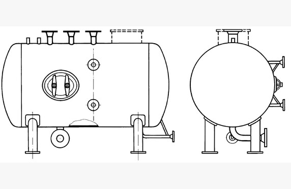
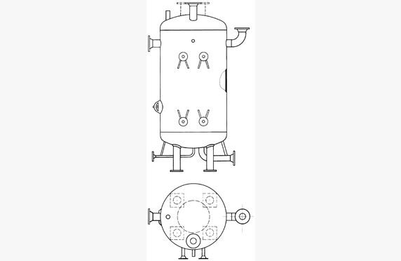
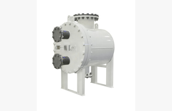
Heat exchangers are a key part of steam and condensate systems. Plate heat exchangers are a common choice due to their good pressure and temperature resistance, heat transfer efficiency, and compact size. Typical applications include heating of domestic or additional water, condensation of saturated steam from turbines, and heat recovery systems for boiler blowdown, flash steam, and flue gas (economizers).

Choosing a steam heat exchanger assembly

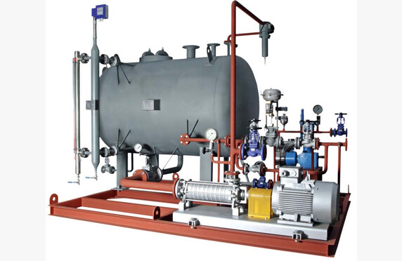
The manufacturing material and sealing method of the heat exchanger can be selected from several options depending on the operating values of the target system, such as medium, pressure, and temperature. Our heat exchanger modules are always dimensioned specifically for the system. A pre-designed module serves as the basis for sizing, speeding up the design work and reducing various product variations. All components of the exchanger module are replaceable and have been selected from our wide range of suppliers to suit the purpose.

Among our principals, for example, Gestra has launched its own ready-made heat exchanger module range consisting mainly of larger tube heat exchangers. The water space of tube heat exchangers is larger, resulting in more stable control behavior of the exchanger heated by process steam.

The sizing of the module requires initial process data from the customer, which includes: thermal power, flow rate, pressure and temperature, medium used, allowable pressure drop, expected contamination factor, and possibly desired overdimensioning.

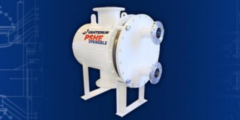
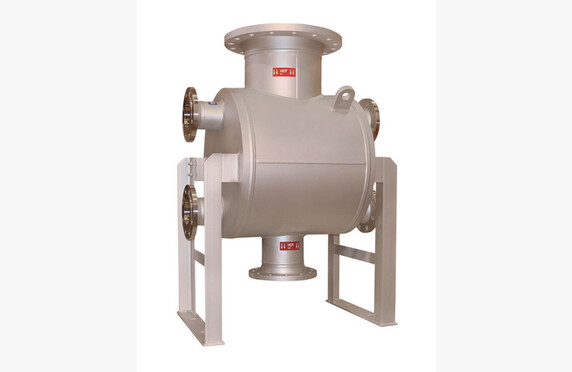
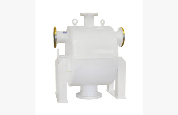
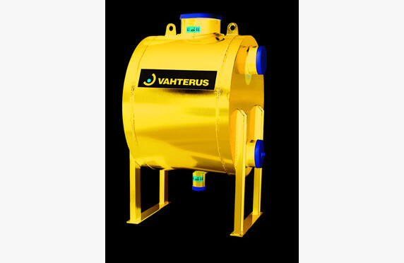
In modules manufactured by Konwell, high-quality, domestic plate heat exchangers made by Vahterus are used, whose features are optimized for plant conditions. Long practical experience and continuous product development have made Vahterus one of the most renowned and high-quality heat exchanger manufacturers in the world, as evidenced by numerous patents and awards for innovative solutions.

The control circuit of the heat exchanger, shut-off valves, and steam traps are selected from the products of German Gestra and Ari Armaturen, whose quality has been proven during Konwell’s decades-long representation.

Depending on the process, the heat exchanger may require, for example, a steam dryer or a separate overheating protection for the exchanger. We also provide such special solutions according to the customer’s needs.

Operation

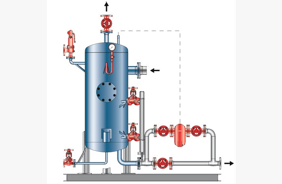
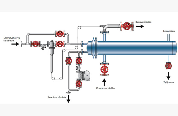
Usually, the shell side of the exchanger acts as a steam space, where process steam is brought based on the set target temperature of the starting line of the medium to be heated. The control of the amount of steam allowed into the exchanger is managed by a separate control valve on the steam inlet side. The valve type can be a self-acting temperature control valve or an electric/pneumatic control valve. In heat exchanger modules for building heating systems, a control valve is sometimes used on the condensate side of the heat exchanger as well. For safety arrangements, self-acting control circuits can be equipped with a self-monitoring temperature limiter, but in electric/pneumatic systems, the safety and warning features are naturally more extensive. The correct selection and sizing of the control valve is a very important part of a properly functioning heat exchanger module.

Especially when starting the process and during large load fluctuations, it must be ensured that water hammer does not occur in the exchanger, meaning sufficient condensate removal must be ensured.

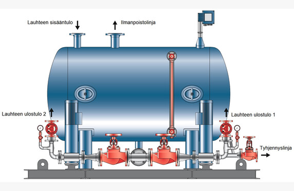
On the discharge side of the heat exchanger, depending on the target, either only a steam trap or a steam trap with an integrated condensate lifter is installed, whose task is to remove the condensed steam that has released its energy in the exchanger to the plant’s condensate removal line. A condensate lifter is needed in situations where the pressure difference between the steam and condensate line is so small that the pressure difference at partial load of the exchanger cannot remove the condensate from the exchanger. When the need for heat transfer decreases and the control valve begins to restrict steam flow, the pressure difference inside the exchanger also decreases. This leads to a deterioration in condensate removal, and the reaction occurs in all heat exchangers regardless of the oversizing of the exchanger. As condensate removal worsens, the condensate surface in the exchanger begins to rise, leading to so-called exchanger fouling.

Some heat exchangers are equipped with a vacuum safety valve to prevent vacuum formation and improve poor condensate removal. However, through the vacuum safety valve, atmospheric gases can enter the system, which act as an insulator in the heat transfer process. When the vacuum safety valve is not used, the gas content and temperature fluctuations of the condensate decrease, leading to improved heat transfer efficiency. Corrosion problems and water hammer in the exchanger module are also eliminated, reducing maintenance costs. Additionally, the need for chemical treatment of process water decreases. We use Vahterus plate heat exchangers designed to withstand vacuum.

Shaft Torque Measurement

Shaft Torque Measurement

VAF vääntövoiman mittaus - torque measurement
VAF T sense vääntömomentin mittaus

Media

Manufacturers

VAF Instruments

Technical Data

Other names: torque measurement, thrust measurement, shaft power measurement, torque measurement

What is Shaft Torque Measurement?

The torque measurement system provides the user with information about the torque and compressive forces acting on the shaft. Based on the measurement results, it is possible to analyze how much power is produced and whether it is transferred entirely to the shaft. The effects of the changes made can be read immediately from the meter. This gives the systems great potential for savings.

Typical applications for torque and compression measurements include ship propeller shafts, where the pitch angles have a significant impact on the forces transmitted to the shaft. By optimizing the pitch angles according to sailing conditions and cargo, fuel savings of up to 5% have been achieved. By measuring thrust, it is also possible to monitor the degree of hull fouling and, from a maintenance perspective, plan hull cleaning at an appropriate time in advance.

Selection of Torque Measurement Devices

The technology used in the VAF TT-Sense measurement system has been awarded the Marine Propulsion Fuel Efficiency Award.

In addition to concrete energy savings, the advantage of torque measurement is its easy installation, which can be carried out as part of the ship’s own maintenance work without specialized expertise. The measurement system can be combined with fuel consumption calculation: up to 12 flow meters equipped with temperature measurements can be connected to the system.

We assist in selecting measurement devices according to the requirements of the application. Ask our contacts for more information.

Download Brochures

download

VAF WP 2101 GB 0317 Measuring the Full Scale Performance of a propeller and bulbous bow retrofit via propeller thrust measurements

Lataa PDF
download

VAF WP 2102 GB 0318 Experience with Full Scale Thrust measurements in dynamic trim optimisation

Lataa PDF
download

VAF TT-Sense 663 GB 0119 Product Bulletin

Lataa PDF
download

VAF T-Sense 660 Product Bulletin

Lataa PDF
download

VAF 2103 White Paper GB 1018 The propeller as a speed log

Lataa PDF
download

VAF 2100 White Paper GB 0416 Fuel Saving Potentials via measuring propeller thrust and hull resistance at full scale

Lataa PDF
download

VAF 660 T-Sense Optical Torque Measurement Systems

Lataa PDF

Conductivity measurement

Conductivity measurement

Media

Steam and condensate

Manufacturers

GESTRA

Technical specifications

Other designations: conductivity measurement

What is steam boiler conductivity measurement?

Conductivity measurement is used primarily in steam boilers to monitor boiler water and condensate. Limit values are set for the quality of the boiler water, which the conductivity measurement monitors. If the water quality deviates from the limit value, the sensor indicates the change to the system, based on which the surface blowdown / boiler conductivity is adjusted.

Proper boiler water conductivity is important not only for the internal condition of the boiler and minimized maintenance, but also because an effective conductivity measurement achieves an optimized water blowdown rate. In this case, as little make-up water as possible is required.

Conductivity measurement can also be used as a leak detector, for example in heat exchangers where two intermediary fluids with different electrical conductivities are used. If a leak occurs in the heat exchanger and the fluids mix, the conductivity sensor immediately triggers an alarm in the system.

Selection of Conductivity Measurement Devices

We assist in selecting measurement devices that meet the application’s requirements. 

GESTRA LRG and LRGT conductivity sensors are available with either manual or automatic temperature compensation. The conductivity signal is forwarded via an active transmitter integrated into the sensor (output signal 4-20 mA) or by using a separate amplifier, which allows digital communication between the sensor and the amplifier. The conductivity of the medium to be measured must be at least 0.5 µS/cm.

GESTRA also offers the LRS 1-7a controller for conductivity sensors, which can, among other things, control a three-way valve to reject dirty condensate.

Contact our representatives for more information.

Download Brochures

download

GESTRA LRR1-50, LRR1-51 Conductivity Controllers

Lataa PDF
download

GESTRA LRR1-52, LRR1-53, URB50 Conductivity Controllers

Lataa PDF
download

GESTRA LRR1-60 Conductivity Controller

Lataa PDF
download

GESTRA LRG16-4 Conductivity Electrodes

Lataa PDF
download

GESTRA LRG16-9 Conductivity Electrode

Lataa PDF
download

GESTRA LRG16-60, LRG16-61, LRG17-60 Conductivity Electrodes

Lataa PDF
download

GESTRA LRGS15-1 Conductivity Switch

Lataa PDF
download

GESTRA LRGT16-3, LGRT16-4, LRGT17-3 Conductivity Transmitter

Lataa PDF
download

GESTRA LRS1-7 Conductivity Switch

Lataa PDF
download

GESTRA LRS1-50 Conductivity Switch

Lataa PDF

Plate heat exchangers

Plate heat exchangers

Media

Gas and fuel
Steam and condensate
Cryogenic media

Manufacturers

Vahterus

Technical specifications

Pressure: from vacuum up to 150 bar
Temperatures: -196 °C…+600 °C
Other names: plate and shell heat exchanger

What is a Plate Heat Exchanger?

A plate heat exchanger is a device in which heat is transferred between two different media. The heat exchanger consists of a plate pack in which the media flow on different sides of the plates.

Welded plate heat exchangers are physically smaller in dimensions compared to tube heat exchangers with the same heat transfer capacity. The installation space required for a plate heat exchanger is only 20–25 % of that required for a tube heat exchanger. The efficiency is high. The welded structure is mechanically robust and is also well-suited for cryogenic conditions.

Choosing a Plate Heat Exchanger

We offer Vahterus’s PSHE (plate and shell) as well as PRHE (plate and ring) plate heat exchangers.

We assist in selecting the sampling solution that meets the requirements of your application. Contact our representatives for more information.

Steel casing pipe

Steel casing pipe

LNG-siirtoputkisto
LNG-kaksoisterasvaippaputken_rakenne

Media

Steam and condensate
Cryogenic media

Manufacturers

FW-FERNWÄRME-TECHNIK

Technical specifications

Insulation: vacuum and wool or vacuum and cryogel
Other names: double‑jacketed pipe, LNG transfer pipe, LNG pipe, steel‑cased pipe‑in‑pipe

What is a steel casing pipe?

The steel casing pipe consists of the actual product pipe and the surrounding casing pipe. After installation, the space between the pipes is evacuated, which improves the thermal insulation. The phenomenon is based on the so‑called thermosiphon effect, where the vacuum prevents heat conduction between the pipes. In addition to the vacuum, insulation is present in the interspace to prevent heat transfer by radiation.

The product pipe is supported by the outer pipe with bearings, resulting in a relatively rigid structure. The pipe can be embedded directly into the ground without concrete pipe wells or, in crossings, a normally longer bridging span can be used.

Steel casing pipe selection

We assist with inquiries and procurement of a steel casing pipe that meets the requirements of your application. For more information, please ask our contacts.

For steam and condensate

A drawback of traditional steam and district heating pipes is their high heat losses over long transfer distances. FW-Fernwärme-Technik GmbH’s steel casing pipe achieves significant energy savings. Its heat losses are approximately 40–50% lower compared to a conventionally insulated steam pipe.

For cryogenic media

The triple-layer FW chamber steel casing pipe designed for cryogenic applications consists of a product pipe, a surrounding chamber pipe, and a protective pipe. The product and chamber pipes of the LNG pipe are made of austenitic stainless steel, thereby preventing cold transition. In ground installations, carbon steel is used as the outer protective pipe.

In addition to the vacuum, a cryogel bound to a fibrous mat is used as insulation. The pipe helps avoid condensation problems because, due to its excellent insulating properties, the outer surface of the outer pipe remains relatively warm. Furthermore, thanks to the vacuum, no condensing water is present in the space between the inner and outer pipes, so the insulation always remains completely dry.

There is insulation in the space between the inner pipe and the chamber pipe. The chamber pipe is supported by bearings on the protective pipe, allowing it to move freely during thermal expansion.

Flash vessel

Flash vessel

VD_paisuntahoyryjarjestelma - flash vessel
VD_paisuntahoyryjarjestelma_varikuva

Media

Steam and condensate

Manufacturers

GESTRA

Technical specifications

Other names: expansion steam tank, flash vessels for condensate recovery

What is a flash vessel?

An expansion steam vessel is designed for all applications where, for example, expansion steam is generated from condensate, boiler blowdown, or hot water. The expansion steam vessel can, for example, capture the heat from the boiler blowdown.

Selection of a flash vessel

We help in selecting the expansion steam vessel that meets the application requirements. Ask our contacts for more information.

GESTRA VD flash vessel

The device consists of an expansion steam vessel, condensate inlet, expansion steam outlet, and condensate outlet connections, as well as several safety and control device connections. GESTRA VD expansion steam vessels are particularly suitable for heat recovery purposes from boiler blowdown. The device is designed and sized according to the operating parameters of the system.

Condensate flows into the vessel through the inlet connection on the side. Thanks to the installation position of the inlet connection, the expansion steam vessel functions like a cyclone separator, forcing the incoming condensate to flow in a spiral within the vessel. The centrifugal force separates expansion steam from the condensate, with a residual moisture content of less than 1 %. Additionally, the rotational effect reduces erosive impacts from the flow, which otherwise would wear out the system components.

The lower part of the vessel is designed so that the condensate being directed to the condensate drain is free of vapor bubbles. VD expansion steam vessels are sized for an operating pressure of 12 bar and maximum temperatures of 200 °C.

The condensate level in the vessel can be visually monitored using an optional magnetic liquid level gauge. If necessary, an optional bypass for the condensate drain can also be installed. The vessel has a separate inspection opening for examining the interior of the vessel.

Pump-driven or electric/electropneumatic condensate drainage systems are available on separate request.

GESTRA VD23/26 flash vessel

VD23 and VD26 expansion steam vessels, together with UNA turbine condensate drains, form a compact expansion steam system. The vessels feature connections for condensate inlet as well as outlets for expansion steam and condensate. The purpose is the separation of expansion steam from the condensate. The vessels are available in both vertical and horizontal models. All expansion steam vessels are sized according to process values.

Condensate is directed into the vessel through a protective plate, whose function is to reduce erosive impacts on the equipment caused by the condensate. The structure of the lower part of the condensate vessel ensures that the condensate is free of vapor bubbles when reaching the condensate drain.

Download brochures

download

GESTRA Flash Vessel VD DBL 818997 01

Lataa PDF

Automated condensate return unit

Automated condensate recovery unit

SDI Lauhteenpalautussäiliö - automated condensate recovery unit
SDL-SDS-mp_lauhteenpalautusyksikko_varikuva
SDL_SDS_hp-lauhteenpalautusyksikko_varikuva
SDR_lauhteenpalautusyksikko_varikuva
SDI_Lauhteenpalautusyksikko_osaluettelolla
SDI_Lauhteenpalautusyksikko_piirroskuva
SDI_Lauhteenpalautussailio_piirroskuva
SDs_lauhteenpalautussailio_piirroskuva

Media

Steam and condensate

Manufacturers

GESTRA
Konwell

Technical specifications

Manufacturing: customized according to customer requirements
Other names: condensate pumping, condensate tank, condensate pump automated condensate recovery unit

What is an automated condensate recovery unit?

The condensate produced from the steam process is collected in a condensate tank. From the tank, the condensate is returned through the air vent by means of a pump controlled via level measurement. The pumping pressure can be adjusted, within the pump’s capabilities, using a shut-off valve and a pressure gauge.

Choosing an automated condensate recovery unit?

Tanks are sized according to the amount of condensate produced by the process, with the capacity of the standard model tanks being sufficient for up to 14,200 liters at 60 m³/h of condensate. For larger capacities, tanks are available by special order.

We assist in choosing the condensate recovery unit that meets the requirements of the application. Please ask our contacts for more information.

Download brochures

download

GESTRA Condensate Recovery and Return System SDI-SDs DBL 818461 01

Lataa PDF