Steam heat exchanger assemblies

Steam heat exchanger assemblies

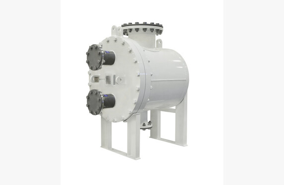
Vahterus_PSHE_levylammonsiirrin_1
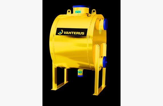
Vahterus_PSHE_levylammonsiirrin_2
Vahterus_PSHE_levylammonsiirrin_4
Gestra_putkilammonsiirrinmoduuli
Vahterus_PSHE_levylammonsiirrin_3

Media

Steam and condensate

Manufacturers

ARI-Armaturen

Technical Specifications

Other names: vapour heat exchanger

What is a steam heat exchanger?

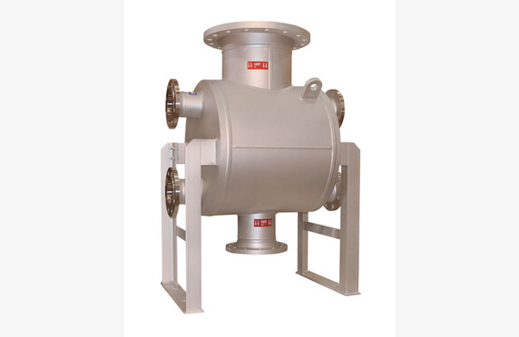
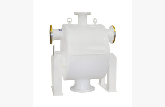
Heat exchangers are a key part of steam and condensate systems. Plate heat exchangers are a common choice due to their good pressure and temperature resistance, heat transfer efficiency, and compact size. Typical applications include heating of domestic or additional water, condensation of saturated steam from turbines, and heat recovery systems for boiler blowdown, flash steam, and flue gas (economizers).

Choosing a steam heat exchanger assembly

The manufacturing material and sealing method of the heat exchanger can be selected from several options depending on the operating values of the target system, such as medium, pressure, and temperature. Our heat exchanger modules are always dimensioned specifically for the system. A pre-designed module serves as the basis for sizing, speeding up the design work and reducing various product variations. All components of the exchanger module are replaceable and have been selected from our wide range of suppliers to suit the purpose.

Among our principals, for example, Gestra has launched its own ready-made heat exchanger module range consisting mainly of larger tube heat exchangers. The water space of tube heat exchangers is larger, resulting in more stable control behavior of the exchanger heated by process steam.

The sizing of the module requires initial process data from the customer, which includes: thermal power, flow rate, pressure and temperature, medium used, allowable pressure drop, expected contamination factor, and possibly desired overdimensioning.

In modules manufactured by Konwell, high-quality, domestic plate heat exchangers made by Vahterus are used, whose features are optimized for plant conditions. Long practical experience and continuous product development have made Vahterus one of the most renowned and high-quality heat exchanger manufacturers in the world, as evidenced by numerous patents and awards for innovative solutions.

The control circuit of the heat exchanger, shut-off valves, and steam traps are selected from the products of German Gestra and Ari Armaturen, whose quality has been proven during Konwell’s decades-long representation.

Depending on the process, the heat exchanger may require, for example, a steam dryer or a separate overheating protection for the exchanger. We also provide such special solutions according to the customer’s needs.

Operation

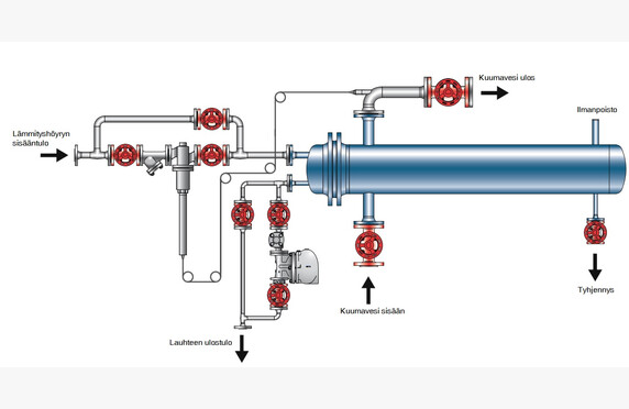
Usually, the shell side of the exchanger acts as a steam space, where process steam is brought based on the set target temperature of the starting line of the medium to be heated. The control of the amount of steam allowed into the exchanger is managed by a separate control valve on the steam inlet side. The valve type can be a self-acting temperature control valve or an electric/pneumatic control valve. In heat exchanger modules for building heating systems, a control valve is sometimes used on the condensate side of the heat exchanger as well. For safety arrangements, self-acting control circuits can be equipped with a self-monitoring temperature limiter, but in electric/pneumatic systems, the safety and warning features are naturally more extensive. The correct selection and sizing of the control valve is a very important part of a properly functioning heat exchanger module.

Especially when starting the process and during large load fluctuations, it must be ensured that water hammer does not occur in the exchanger, meaning sufficient condensate removal must be ensured.

On the discharge side of the heat exchanger, depending on the target, either only a steam trap or a steam trap with an integrated condensate lifter is installed, whose task is to remove the condensed steam that has released its energy in the exchanger to the plant’s condensate removal line. A condensate lifter is needed in situations where the pressure difference between the steam and condensate line is so small that the pressure difference at partial load of the exchanger cannot remove the condensate from the exchanger. When the need for heat transfer decreases and the control valve begins to restrict steam flow, the pressure difference inside the exchanger also decreases. This leads to a deterioration in condensate removal, and the reaction occurs in all heat exchangers regardless of the oversizing of the exchanger. As condensate removal worsens, the condensate surface in the exchanger begins to rise, leading to so-called exchanger fouling.

Some heat exchangers are equipped with a vacuum safety valve to prevent vacuum formation and improve poor condensate removal. However, through the vacuum safety valve, atmospheric gases can enter the system, which act as an insulator in the heat transfer process. When the vacuum safety valve is not used, the gas content and temperature fluctuations of the condensate decrease, leading to improved heat transfer efficiency. Corrosion problems and water hammer in the exchanger module are also eliminated, reducing maintenance costs. Additionally, the need for chemical treatment of process water decreases. We use Vahterus plate heat exchangers designed to withstand vacuum.
Sample cooler

Sample cooler

Media

Steam and condensate

Manufacturers

GESTRA
Konwell
Valsteam ADCA

Technical specifications

Other names: sample cooler

What is a sample cooler?

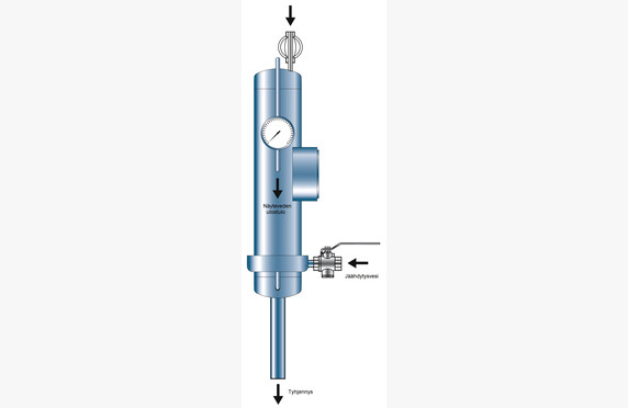
Sample coolers are designed specifically for taking boiler water samples. It prevents the re-vaporization of the sample, which is both dangerous and leads to inaccurate measurement results. Sampling is a particularly important part of the operation of steam boilers. However, proper and uncontaminated analysis requires the right sampling method and equipment that function correctly.

Selecting a sample cooler

We assist in selecting a sample cooler that meets the requirements of your application.

Direct sampling from hot boiler water and pressurized lines always carries the risk that the procedure may not be performed correctly. Re-vaporization of the sample in the sampling line or sample tank increases the density of the remaining sample water; for this reason, the sample no longer represents the boiler’s true TDS content (salinity). Vaporization of the sample inevitably leads to incorrect measurement results.

The sample coolers we supply have been developed for reliable and user-friendly boiler water sampling. The boiler water sample is cooled to a reference temperature of 25 °C, thereby meeting the basic requirements for accurate water analysis.

Contact our representatives for more information.

Download brochures

download

Konwell Sample Cooler DS

Lataa PDF
download

ADCA SC332, SC432,SC532 Sample Coolers

Lataa PDF

Process controllers

Process controllers

Media

Steam and condensate
Process media

Manufacturers

JUMO

Technical Specifications

Other designations: controllers and signal converters

What are process controllers?

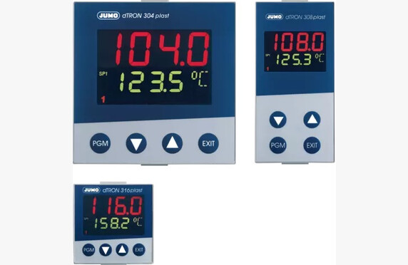
In process control, various controllers are required. dTRON unit controllers are excellently suited for the regulation of pressure, temperature, and level.

Process controller selection

Our standard model is the 48×96 universal unit controller. We assist in selecting devices according to the requirements of the application. Ask our contacts for more information.

Download Brochures

download

JUMO dTRON 304 308 316 Compact Controller

Lataa PDF

Energy calculation and compensation units

Energy calculation and compensation units

Media

Steam and condensate
Natural gas, biogas and biomethane
Process media
Gas and fuel

Manufacturers

METRA Energie-Messtechnik

Technical Specifications

Supply voltage: 24 V DC or 230 V AC
Analog inputs: 2-4 pcs
PT inputs: 2 pcs
Digital inputs: 2-6 pcs
Analog outputs: 2-6 pcs
Digital outputs: 3-7 pcs
Interfaces: M-Bus, RS232, RS485, Ethernet, Profibus DP
Protocols: M-Bus, Profibus DP, Modbus (ASCII, RTU, TCP/IP)
Other designations: calculation and compensation units

What are Energy Meters and Compensation Units?

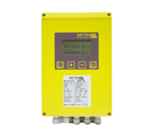
Flow meters provide their measurement results based on the pressure and temperature values set on them. In reality, however, the process values can fluctuate on both sides of the set values, and the role of the compensation units is to perform this correction. Especially in billing applications, it is important to know the flow rate very accurately. 

The calculation unit determines the values for volumetric and mass flow as well as energy. To achieve high precision, pressure- and temperature-dependent variables are continuously corrected.

Selection of Energy Meters and Compensation Units

The meters are delivered either as panel-mounted units or as ready-to-install wall-mounting enclosures. We assist with the selection of equipment according to the requirements of the application. Ask our contacts for more information.

For Steam and Condensate

METRA ERW 700 meets the calculation requirements for steam billing measurements in accordance with SFS-EN ISO 5167.

The meter comes pre-programmed with a flow calculation equation, discharge coefficients for pressure difference devices for different opening ratios and measurement methods, as well as expansion coefficients for various media.

The IAP WS IF 97 steam tables are used in the calculation.

Metal expands when heated. In billing measurements, temperature changes are taken into account by adjusting the size of the flow opening of the pressure difference device based on the temperature measurement and the pre-programmed thermal expansion coefficient.

In energy calculations, the energy of the returning condensate can also be taken into account and deducted from the total energy consumed.

For Process Fluids

METRA ERW 700 is a MID-approved unit for calculating flow and energy of district heating.

The calculation unit receives the flow rate and temperature(s). Based on the data, the consumed energy is calculated.

The specific heat capacity of a water/glycol mixture is different from that of water.

In heating/cooling systems that use a water/glycol mixture, the specific heat capacity of the medium can be programmed. The specific heat capacity of a water/glycol mixture depends on the temperature and deviates significantly from that of water.

The specific heat capacity of the medium can be programmed into the ERW 700 energy meter, ensuring the accuracy of the energy calculation.

For Gases and Liquid Fuels

The volumetric flow of liquid fuels can be converted to mass flow by taking temperature into account and calculating the density at the measured temperature.

Measurement of natural gas quantity is based on the measurement of volumetric flow. Due to compressibility, in addition to the measured volumetric flow, the prevailing pressure and temperature conditions during measurement must be considered. The measured volumetric flow of natural gas is converted to normal conditions (0 ºC and 1.01325 bar). In precise measurements, a compressibility factor is also taken into account, because natural gas behaves somewhat differently from an ideal gas, especially at higher pressures.

The calculation methods used for gaseous media are:

  • ideal gas law
  • Redlich-Kwong
  • GERG 88
  • flow correction taking temperature, pressure, and compressibility into account

The METRA ERW 700 calculation unit determines the values for volumetric and mass flow as well as energy. To achieve high precision, pressure- and temperature-dependent variables are continuously corrected.

Download Brochures

download

METRA ERW 700 Electronic Flow Computer

Lataa PDF

Ultrasonic flowmeters

Ultrasonic flowmeters

Metra ultrasonic flow meter
Metra ultrasonic flow measurement
Metra ultrasonic flow meter for hot and cold

Media

Steam and condensate
Process media

Manufacturers

Intra-Automation
METRA Energie-Messtechnik

Technical Specifications

Size classes: DN 15-1000
Pressure classes: PN 40
Materials: carbon steel
Connection ends: flanged, threaded
Temperature range: max. 200 °C
Other names: ultrasonic flow meters

What is an ultrasonic flowmeter?

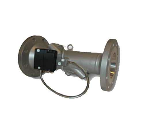
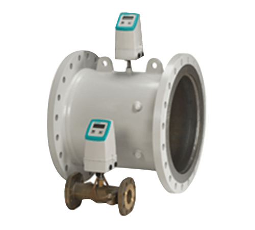
Ultrasonic meters are used for measuring liquid flow.

The measurement is based on the travel time of sound in a known liquid. The ultrasonic flowmeter sends an ultrasonic signal into the pipe to be measured while also receiving the return signal. When the pipe size and the speed of sound in the flowing medium are known, the flow rate of the medium can be calculated based on the obtained signal.

Choosing an Ultrasonic Flowmeter

Ultrasonic flowmeters are also available in battery-operated form, which reduces installation costs in locations where electricity is not readily available.

Measurement is also possible from the top of the pipe.

In addition to the measurement that is introduced into the pipe, there is also measurement from the surface of the pipe. The sensors are installed at a distance from each other, as specified in the instructions for use depending on the pipe’s diameter, so that the pipe does not have to be drilled. This is also suitable for temporary verification measurements. However, the surface measurement is always performed in such a way that the pipe is full of the liquid being measured.

We assist in selecting an ultrasonic flowmeter that meets the requirements of the application. Ask our contacts for more information.

Download Brochures

download

Intra-Automation Ultrasonic Flowmeter Type IS210-S

Lataa PDF

Magnetic flowmeters

Magnetic flowmeters

Media

Steam and condensate
Process media

Manufacturers

Bopp & Reuther Messtechnik

Technical Specifications

Size ranges: DN 15-2000
Pressure classes: PN 6-40
Body materials: carbon steel, stainless steel, Hastelloy
Electrode materials: Hastelloy, platinum-coated stainless steel, titanium
Lining: soft rubber, hard rubber, PTFE/PFA
Accuracy: ±0.25% of the measured value, ±0.1% of the full-scale value
Special features: empty pipe detection, third grounding electrode optional, bidirectional measurement, direct output 4–20 mA, pulse output, Modbus (RTU & ASCII), battery-powered solutions available
Other names: magnetic flow meter

What is a Magnetic flowmeter?

Magnetic flowmeters are used for electrically conductive liquids with a conductivity of at least 5 µs/cm.

The measurement is based on electromagnetic induction. Electromagnets create a magnetic field; when an electrically conductive medium flows through the magnetic field, it induces a voltage. The voltage increases as the flow increases according to the following formula:

U = B*I*V
U = induced voltage
B = magnetic flux density
I = distance between the measuring electrodes
V = flow velocity of the medium

Selection of the magnetic flowmeter

In addition to a wide measurement range, magnetic flowmeters are a relatively cost-effective method for liquids.

The measuring tube is normally lined with rubber or Teflon, but it is also available without lining for corrosive applications.

We assist in selecting a remote control device that meets the requirements of the application. Ask our contacts for more information.

Download Brochures

download

Bopp u0026 Reuther SpiraMAG Electromagnetic Flowmeter

Lataa PDF

Differential pressure-based flow measurement

Differential pressure-based flow measurement

Paine-erovirtausmittari EWZ_1271
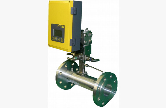
Metra EDZ_1501 paine-eromittari - differential pressure meter

Media

Steam and condensate
Process media

Manufacturers

Bopp & Reuther Messtechnik
METRA Energie-Messtechnik

Technical specifications

Sizes: DN 15-1000
Pressure classes: PN 10-320
Materials: carbon steel, acid-resistant steel, high-strength steels
Other names: differential pressure-based measurement

What is differential pressure-based flow measurement?

When the medium is constricted, the pressure difference is increased. By measuring this pressure difference and relating it to the density of the medium and the pipe size used, the flow rate can be calculated using the pressure difference.

The measurement is suitable for liquids, gases, and vapours.

Selection of the differential pressure flow meter

Differential pressure measurement is an old, comparatively simple method of flow measurement.

Our BOPP&REUTHER and METRA differential pressure devices can be delivered either as separate installations or compactly with the differential pressure transmitter installed directly in the measurement run.

In billing applications, measurement is primarily carried out using methods in accordance with the standard SFS EN 5167.

The measurement methods in accordance with the SFS EN 5167 standard are:

  • orifice plate (constriction plate)
  • flow nozzle (ISA-1932)
  • Venturi nozzle
  • Venturi tubes

The standard specifies:

  • the structure and manufacturing method of the pressure device
  • the flow rate calculation equation
  • the discharge coefficients for differential pressure devices for various orifice ratios and measurement methods
  • the expansion factor for gaseous media
  • the straight-run lengths before and after the differential pressure device

In few processes are pressure and temperature constant. For this reason, the medium’s density ρ must be compensated based on temperature and pressure. Compensation can be done either directly in the differential pressure transmitter or by using a separate compensation unit.

Metal expands when heated. In billing applications, temperature changes are taken into account by adjusting the size of the differential pressure meter’s flow opening based on temperature measurements and a pre-programmed thermal expansion coefficient.

Optionally, METRA’s differential pressure transmitters can be equipped with an automatic zero point calibration module. This significantly prolongs the maintenance of measurement accuracy and reduces the need for device calibration.

Download brochures

download

METRA EDZ / EWZ 110.1 / 117.1 Flow/Energy Meter

Lataa PDF
download

METRA EDZ/EWZ 150.1 and EDZ/EWZ 157.1 Flow/Energy Meter for Technical Gases

Lataa PDF
download

METRA EDZ/EWZ 1×0.1 and EDZ/EWZ 1×7.1 Flow/Energy Meter for Vapours, Liquids and Technical Gases

Lataa PDF

Vortex flowmeters

Vortex flowmeters

Media

Steam and condensate
Process media

Manufacturers

Bopp & Reuther Messtechnik

Technical specifications

Sizes: DN 15-300
Pressure classes: PN 16-100
Materials: AISI 316, steel, hastelloy
Temperatures: -40 °C…+400 °C
Accuracy: ±0.6 %
Other names: vortex flow meter

What is a vortex flowmeter?

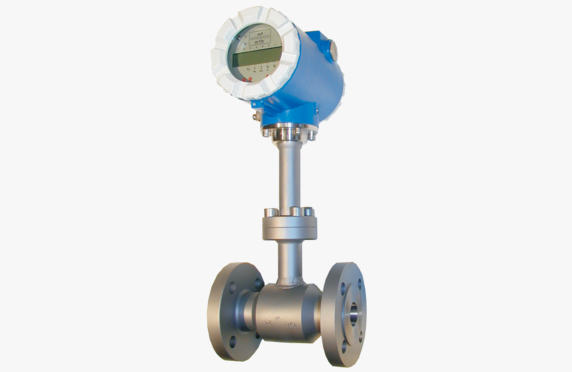
Vortex flowmeters have a bluff body that causes vortices to form alternately on both sides of the obstruction. The frequency of the vortices is proportional to the flow velocity. The volumetric flow rate can be calculated from the flow velocity when the pipe diameter is known.

The advantage of vortex measurement is its simplicity, versatility, and affordability. It is suitable for many applications.

Selection of vortex flowmeter

Vortex meters are suitable for measuring low-viscosity liquids and gases.

The electronics can also be supplied separately, allowing the meter to be used at high temperatures. Both flange-mounted and between-flange models are available.

We assist in selecting a vortex flowmeter that meets your application requirements. Contact our representatives for more information.

Download brochures

download

Bopp & Reuther Vortex Meter VTX3 datasheet

Lataa PDF

Turbidity monitoring

Turbidity monitoring

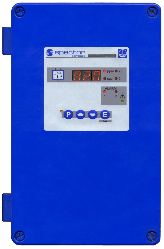
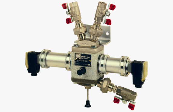
GESTRA ORT6-02-5MB2 Turbidity Detector
Öljyn ja sameuden mittaus - turbidity measurement

Media

Steam and condensate
Process media

Manufacturers

GESTRA

Technical specifications

Pressure and temperature: PN 10, 120 °C
Materials: GG-25, 1.4580
Measurement range: 0-25 ppm
Operating voltage: 230 V, 48-62 Hz, optionally 110 V
Output: 0/4-20 mA
Other names: turbidity monitoring

What is turbidity monitoring?

The measurement of oil and turbidity is based on an in-line intermediate sample drawn from the process, which is passed through the meter and then returned to the process. A light signal is passed through the medium, with its refraction in a clean medium known.

Selection of turbidity monitoring devices

For example, in condensing systems the meter checks the purity of the condensate. In several industrial processes where product tanks are heated with steam, there is a risk that if the heating coils burst, a foreign substance such as oil flows into the condensate system. Upon detecting a change in the purity of the condensate, the GESTRA OR oil and turbidity sensor immediately sends information to the control room and triggers, for example, a 3-way valve in the line to divert the dirty condensate to a reserve container.

This ensures that information about an abnormal condition is received quickly, and the oily condensate does not contaminate the entire condensate system.

GESTRA OR 52 is designed for continuous monitoring of turbidity, emulsified oil, and fat content in liquids.

Applications include monitoring the oil content in condensate from steam boiler plants as well as overseeing sand filters, reverse osmosis, and mineral removal in water treatment plants. Other applications include wastewater treatment plants and the beverage industry, among others.

We assist in selecting turbidity monitoring devices that meet the requirements of your application. Contact our representatives for more information.

Download brochures

download

GESTRA OR52-5 OR52-6 Turbiscope Datasheet

Lataa PDF

Pressostats and thermostats

Pressostats and thermostats

Media

Steam and condensate

Manufacturers

Danfoss

Technical data

Other names: pressure switches, temperature switches, pressostats, thermostats

What are pressostats and thermostats?

Pressostats, also known as pressure switches, and thermostats, also known as temperature switches, are process safety switches that shut the device down when a limit is exceeded. The pressure switch receives its signal from pressure while the thermostat from temperature.

Typical applications for a pressure switch include acting as a pressure limiter for a steam boiler. If the pressure rises too high, the pressure switch shuts off the pressure supply. Similarly, it operates as an on-off control for a pump.

Typical applications for a thermostat include, for example, acting as temperature limiters for pipelines or as forced controls for systems, whereby the thermostat sends a signal when the cooling water supply exceeds the set temperature.

Selection of pressostats and thermostats

We assist in selecting devices that meet the requirements of the application. Through us, Danfoss RT pressostats and thermostats are available.

Ask our contacts for more information.

Download brochures

download

Danfoss Pressure Switch Type RT

Lataa PDF
download

Danfoss Thermostat Type RT

Lataa PDF