Other: operating point up to 60 meters from the valve, allows cable bends, fire-resistant cable Alternate names: remote cable drive valve operator
What is a valve remote control device?
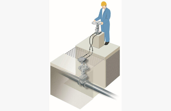
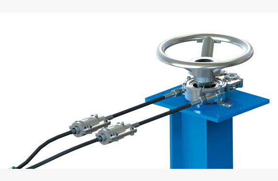
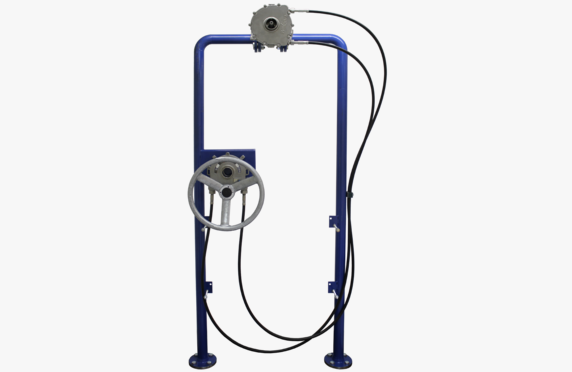
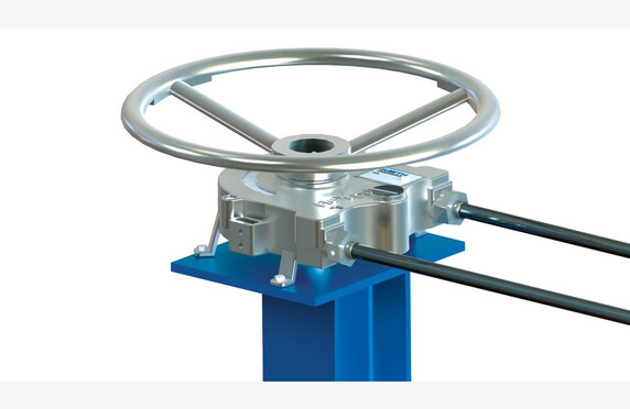
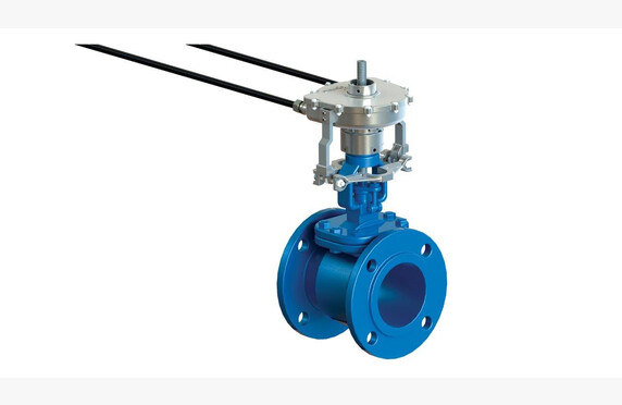
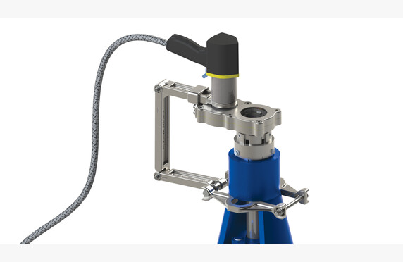
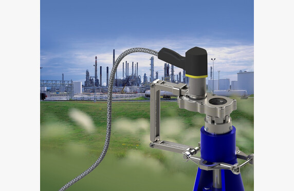
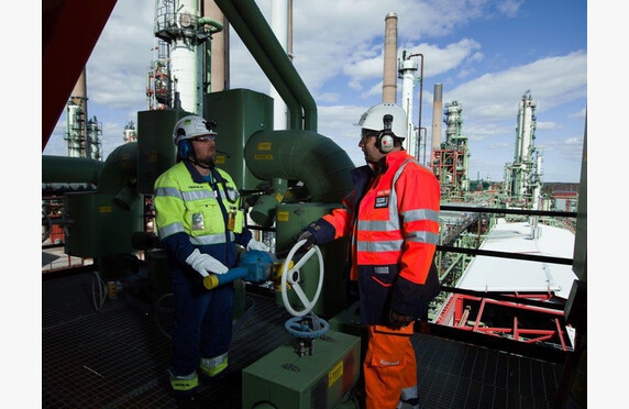
With a remote control device, valves located in dangerous or otherwise difficult-to-access places can be easily operated. The remote control device consists of two gear-driven operating units and a cable running between them. One operating unit is installed on top of the valve to be operated and the other where the valve is intended to be controlled from.
The remote control device is suitable for all valve models, whether screw or hand lever operated, and it is easy to install afterwards on an existing valve.
Selecting a valve remote control device
When constructing systems, valves cannot always be placed in locations optimal for operation; they are sometimes located on high pipe bridges, in low, narrow piping tunnels, or in areas where environmental conditions pose their own challenges to the normal operation of the valve.
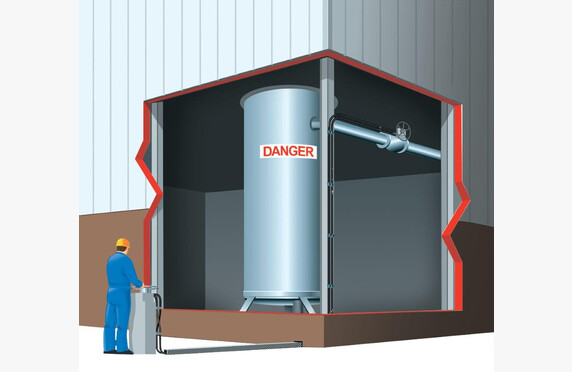
If a valve placed in a challenging location is operated infrequently, its automation may be too costly. It is precisely for such cases that Smith Flow Control’s FlexiDrive manual remote control device, part of the Sofis Group, has been designed.
Thanks to the flexible cable, the operating point can be positioned up to 60 meters away from the valve itself. FlexiDrive installation sites may also include turns and bends of up to 720 degrees, which are not possible with chain wheels and extension bars.
In addition to the aforementioned pipe bridges, installations have been made on valves mounted on the walls of large terminal tanks and in the confined spaces of icebreakers. Installations have also been carried out, for example, in a nuclear power plant, where the operated valves are on the so-called radiation side and the operation is desired to be brought to a safe area.
We help select a remote control device that meets the requirements of the application. Ask our contacts for more information.
Heavy valves used in various industrial processes pose a challenge, especially from a safety perspective. Different types of turning levers are used, and unfortunately, minor – and sometimes even major – workplace accidents occur. Not to mention that operating a large wedge-slip valve from one extreme position to another is quite strenuous. Valve operating tools can make valve operation easier and safer.
Choosing a portable valve actuator
A new valve might be light, but over time it becomes heavier and heavier. Lubrication no longer helps, and replacement or automation is expensive.
We have good experience performing valve open and close operations using the operating tool.
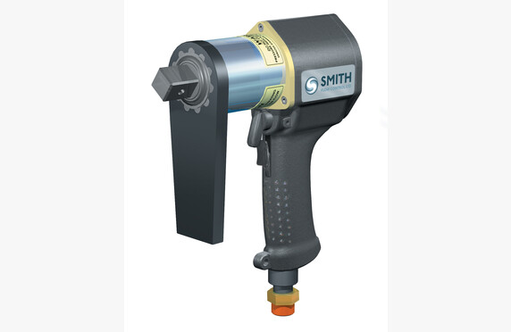
There are two options available. In both cases, for example, compressed air is used as the power source, which easily provides the required torque.
See presentations for both options.
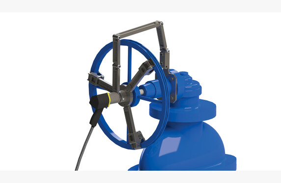
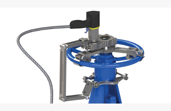
The advantage of the EasiDrive featured in the video is that it is a small, handy tool. It features a fixed platform that is mounted on top of any existing valve. You can see various options in the photographs above. The tool—the gun—is placed on this platform, and with a press of a button, you can operate the valve to open or close. The device has its own adjustment for the applied torque.
The advantage of the Power Wrench featured in the video is that no fixed platform for the tool is required; instead, as the video shows, the platform can be easily mounted onto the existing valve handwheel.
If you are interested in testing the device at your facility, we are happy to perform a demonstration. We have both tools in stock.
Other designations: Lockout, Tagout, Master lock, valve safety locks
What is a valve lockout system?
Work safety is fundamentally linked to the safe operation of processes. According to statistics, numerous industrial accidents are caused by so‐called human errors in operation. Either the wrong valve is operated, or it is assumed that the process valves are in a different position than they actually are.
To prevent such human operational errors, a program was developed in the United States by The Occupational Safety and Health Administration (OSHA) called The Control of Hazardous Energy Source Standard, which now serves as an international standard for managing accident risks. In Finland, the concept known as Lockout/Tagout has become a useful term, which simply means reliably disconnecting the energy supply (Lockout) and marking the disconnection (Tagout).
At its simplest, incorrect operation can be attempted to be prevented by a “do not turn” sign, or by tying something to the valve that obstructs, or at least slows down, operation—a rope or some other contraption. However, safety locking is only considered achieved when operation is prevented by some type of lock. On this site, we present various options for implementing safety locks, ranging from simple chain locks to advanced Interlock safety locks, which can also create sequential orders for operating multiple valves.
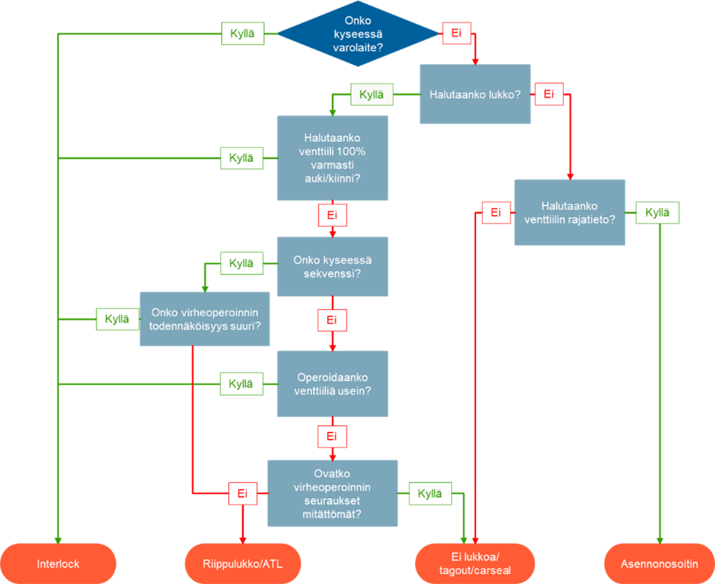
Selection of a valve lockout system
The following flowchart helps determine whether a lock is needed at all for the target, and if so, what kind. For example, if it concerns a safety device, such as a dual-redundant safety valve, Tukes has determined that a chain lock does not eliminate human operational errors, but that an Interlock sequence is required at the site. The same applies if it is important that the valve is definitely 100% open or closed after operation.
By “sequence” it is meant that several valves are operated in a planned order one after the other. In these cases as well, the Interlock safety lock eliminates “human errors”.
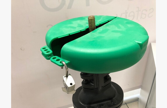
Various locking cable locks or protective covers that lock hand wheels are simple and cost-effective ways to perform valve LOTO (Lockout/Tagout) safety locking. Lockout/Tagout means reliably disconnecting the energy supply (Lockout) and marking the disconnection (Tagout).
From Cable Lock to Hand Wheel and Handle Protective Cover
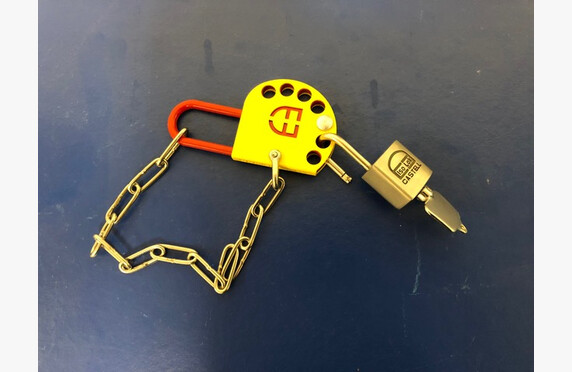
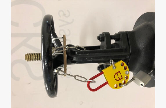
A Lockout/Tagout (LOTO) lock can be created by tying the valve’s hand wheel with a cable so that its operation becomes impossible. At its simplest, it can be implemented using CarSeal straps designed for industrial use, which operate on the principle of a cable tie and are therefore disposable.
A more advanced version is various cable locks that are secured with a mechanical key lock. The cables can be either fixed-length or adjustable. Multiple locks can be attached to a single cable, which can, for example, be color-coded to ensure that the lock is secured by two or more persons. The keys can be personalized so that a particular department or even an individual has their own lock, with which they lock and are the only one who can remove it.
The possibilities for key codings are unlimited.
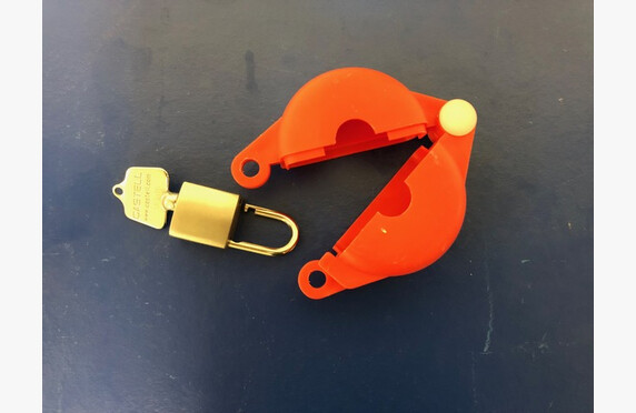
Another option for performing the lock is to prevent the valve operation by protecting and mechanically locking the hand wheel or handle with a protective cover. In this case, the key system works the same as in chain locks.
Not only valves, but various other targets, such as electrical systems, can be locked with mechanical locks.
For managing keys and locks, our software offers various storage cabinets. An essential part of the LOTO system is the marking (Tagout) that must be performed in connection with the locks (Lockout), so that incoming personnel observe and understand that a part of the process has been intentionally isolated from normal operation.
These marking supplies are also available in our product range.
Valve interlocks
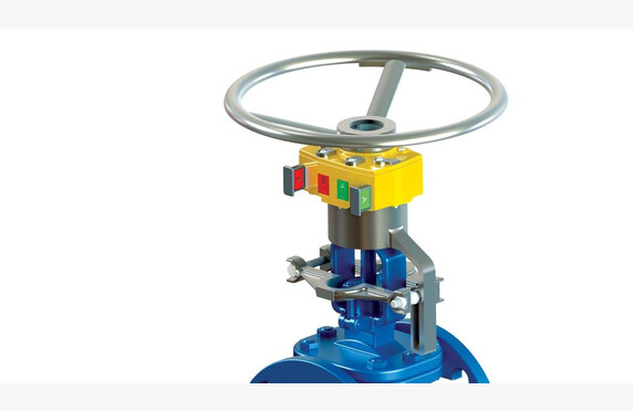
A more advanced method to lock a valve is the interlock. It eliminates the risks of manual operation by enforcing a pre-planned operational order, thereby ensuring the safety of both the process and the worker. The manufacturing of Interlock safety locks is handled by process safety equipment manufacturer Sofis.
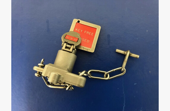
How does the interlock work?
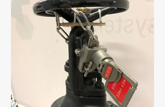
In a safety lock, a locking device is installed over either an existing or a new valve, which operates with a separate key. The key is typically stored in a dedicated key cabinet in the production facility’s control room. Without the key, the safety lock cannot be operated.
The keys for safety locks are typically marked with both text identifiers and color codes. The color code provides an at-a-glance indication of whether the valves in the process are in their default or abnormal positions.
It is even possible to automate the key management system. This is explained in more detail in our blog post.
See the operation of the locking device and an example of color coding in this video.
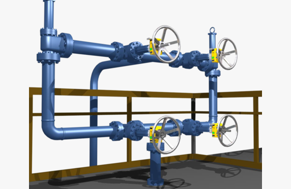
System locking options – sequences
Operations in processes often require that multiple valves be operated consecutively. In such situations, the strengths of interlock safety locks come to the forefront. It should be noted that, for example, TUKES has begun to require that in tanks with several safety valves, it must be ensured that not all backup devices are accidentally closed at the same time. This assurance is easily achieved with an Interlock locking system.
See a sequence example in the video.
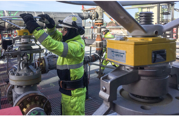
Installation on existing valves
The Interlock safety lock is suitable for all valve models – including actuator-controlled valves – and for all nominal sizes. It is also easy to install retroactively. In such cases, our installers will measure the end-to-end dimensions of the old valve, upon which the factory manufactures an adapter piece to be placed between the locking device and the valve. Our installation team has undergone official factory training, so the installation and adjustment of safety locks is handled with ease.
We have also held a webinar on interlock safety locks, which you can watch below.
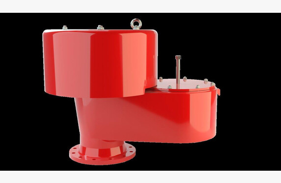
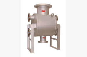
The pressure and vacuum relief valve equalizes the pressure fluctuations occurring in the process. The process is designed to operate within certain limits, and if these are exceeded, the function of the overpressure valve is to release the excess pressure, and similarly the function of the underpressure valve is to relieve vacuum by introducing air at normal pressure into the process. The overpressure valve operates like a safety valve (link to safety page), but it is presented separately because, when an over- or underpressure valve is installed as the tank breathing valve, the set pressures are very low, and therefore the valve’s design differs greatly from that of a conventional safety valve.
At the end of the page, we present our underpressure valve solution separately.
Tank vent valves, also known as breathing valves
Inside large terminal tanks there is a continuous rise and fall in pressure as a result of changes in the outdoor temperature. The same occurs when tanks are being loaded or unloaded. These pressure fluctuations are equalized by what are called breathing valves or over- and underpressure valves, whose set pressures are typically only a few tens of millibars.
Various large tanks could be built so robustly that they would withstand, for example, the temperature fluctuations caused by changes in outdoor air as well as the pressure fluctuations generated during pumping and loading phases, but that is not economically justified. It is more cost-effective to install an over-/underpressure valve, i.e. a breathing valve, on top of the tank.
Breathing valves can be installed on top of the tank, allowing it to breathe ambient air and also draw in makeup air or line air, whereby the outlet gases are routed, for example, to a collection tank.
The valves can be arranged to have a complete vapor barrier so that, for example, the outlet gases from sulfur or bitumen tanks do not disturb the valve diaphragm but are expelled as gas.
Selection of the tank vent valve
We want to highlight three arguments when a purchasing decision is being made.
The first is tightness.
This is important because the tank contains intermediates that are harmful to the environment and, moreover, are valuable. The video below concretely demonstrates the significance of tightness.
The second competitive advantage in the PROTEGO range is the high-rise diaphragm construction, which allows the valve to be set to open only 10% before it must be fully open. In this respect, the breathing valve differs from a safety valve, meaning that for tanks’ over-/underpressure valves operating at low pressures, it is important that the valve is 100% open at the design pressure. The set pressure is then calculated retroactively from this.
In so-called traditional models, the valve begins to open 40% (or in certain models 100%) before reaching full open position. Thus, when the conventional valve starts venting gases to the outdoor air, the high-rise construction of the PROTEGO valve keeps it closed. For example, when using nitrogen, it is important that expensive nitrogen gas is not unnecessarily vented to the outside.
Among other things, we demonstrate this feature in the video below.
Ease of Maintenance as the Third Purchasing Criterion
When it comes to a tank safety device, it is important that the equipment is also well maintained. Almost every year in Finland there are unfortunate news stories about tanks that have failed because, for example, the retaining bow had become adhesively stuck to the seat.
Similarly, our sales team assists with equipment selection. In the case of breathing valves, not only is proper sizing extremely important, but also the choice of equipment. The PROTEGO range is extensive and includes solutions for, among other things, cryogenic and extremely cold intermediates.
Likewise, for sticky intermediates such as styrene, there are dedicated solutions.
And naturally, references from Finland can be found for all of these.
Interested? We are happy to provide additional information and complimentary small-scale training via the Teams application.
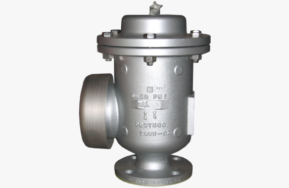
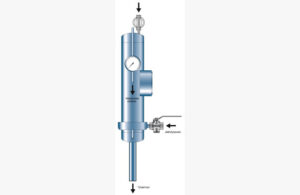
Underpressure Valves
Over- and underpressure can occur in any process, and depending on the process parameters, different protective measures can be taken. A safety valve (link to safety page) can be installed on the line, or an overpressure can be controlled by a self-acting pressure hold valve (link to pressure hold valve page).
An underpressure situation in the process can occur, for example, in oversized heat exchangers when steam condenses rapidly, and at the same time a possibly oversized control valve closes completely. When the natural pressure difference in the system becomes negative, it is exposed to water hammer when condensate removal stops. In some cases, a vacuum protection may function as a problem solver in such situations.
In this case, the underpressure valve can be spring-loaded, so that the valve opens when the vacuum exceeds a predetermined limit, allowing makeup air into the device.
ARI Armaturen’s AWH steam and condensate manifolds are compact combinations designed for relatively small flow rates, in which shut-off valves are integrated into the manifold body. They can feature either packing or metal gasket seals. The valves are fully maintainable, as the valve bonnet and the internal disc are replaceable, should the valves begin to leak due to deposits.
Steam and condensate manifolds are suitable, for example, for distributing steam used in steam tracing and for collecting the resulting condensate.
Selection of steam and condensate manifold
Steam and condensate manifolds are available in both vertical and horizontal installations. In the vertical manifold, the secondary connections are on both sides, and in the horizontal manifold they are only on one side. The lengths of the manifolds and the valve spacing can be customized on a case-by-case basis.
An insulation jacket is available as an accessory, allowing for external installation without the need for an additional protective enclosure.
Steam and condensate manifolds for large condensate volumes are designed and manufactured on a case-by-case basis.
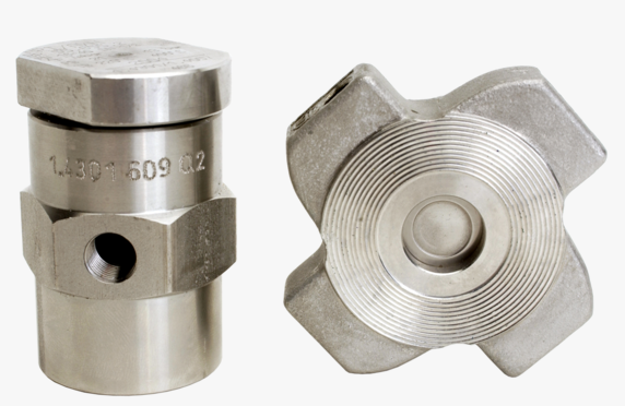
Size classes: DN 15-500 Pressure classes: DIN PN 16-160, ANSI 150-2500 Materials: A105 (C22.8), WCB 1304, 316, 316T, Hastelloy B or C, titanium, duplex Seals: Pentafite (self-lubricating metal seal), stellite Operating temperatures: -148 °C…+800 °C Connection ends: between flanges, flanged, threaded, weld ends Other: several options for hard-coated balls Other designations: metal seated ball valve
What is a Metal Seated Ball Valve?
Metal seated ball valves are an excellent choice when a valve is required to have rapid operating capability and light weight, while also offering high temperature resistance.
Since process media come in many varieties and pressures combined with high temperatures can be very challenging, it is absolutely essential that the function and material of every individual component of the metal seated ball valve are carefully considered and selected.
Selection of the Metal Seated Ball Valve
An extensive range of pressure, temperature, and material options, along with the long experience of our equipment manufacturers, assists in selecting a cost-effective valve for different process applications.
Valves are available in 2-way versions for on/off operation and 3-way versions for diverting services. Antistatic properties comply with the BS 5146 standard and the construction with TA-Luft TÜV.
Our ball valves are available with manual, pneumatic or electric actuators.
PENTA Valves’ valves generally adhere to the Fire Safe EN ISO 10497 – API607 V test requirements. Antistatic properties, in turn, comply with the BS 5146 standard and TA-Luft TÜV.
In our program, you can find valves from manufacturers such as OMB Spa, PENTA Valves, and ARMATURY Group.
ARMATURY Group’s (AG) metal seated ball valve with a movable seal (see brochure) in size classes DN 200–1400 is supported in its design. It is ideally suited for consuming or small molecule media, because the ball and the seal do not slide against each other. When opening, the ball and the seal separate linearly before the ball rotates – the reverse occurs when closing. The seal surface is controlled by the actuator.
The seal is pulled away from the ball prior to operation, minimizing wear and operating torque. Once the valve is closed, the seal is pressed against the ball. The sealing force does not depend on the pressure difference, so the valve achieves full tightness even at very low pressure differences.
The valve is excellent for dry and difficult-to-seal gases, as the seal and the ball do not slide against each other and the sealing force is always high.
We assist in sizing and selecting the appropriate ball valve for each application.
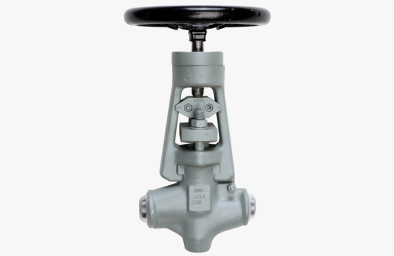
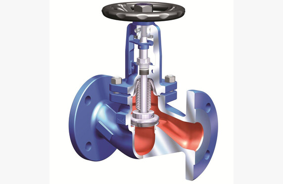
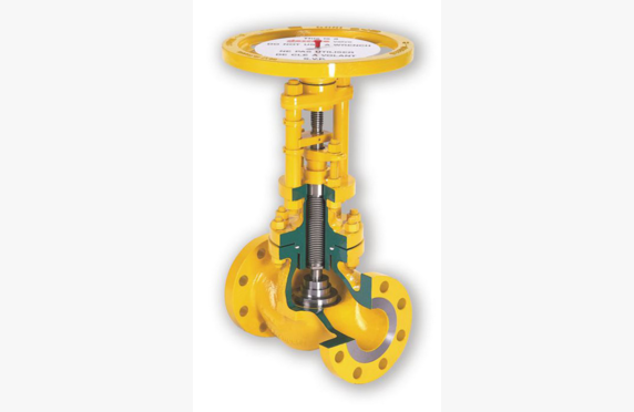
Manually operated globe valves are durable shut-off valves. Their sealing element consists of a wedge-shaped disc that seals tightly against the seat. Globe valves cause a slight pressure drop in the pipeline, which is important to consider when selecting a valve. Globe valves open slowly, preventing pressure surges. Globe valves are categorized into packing-sealed and jacket-sealed valves.
The jacket seal is a kind of double safety measure in addition to the packing seal, preventing stem leakages and fugitive emissions. This is an excellent feature when considering valve maintenance requirements and the valve’s suitability for hazardous fluids such as hot oil, chlorine, or hydrofluoric acid. The jacket prevents process fluid from reaching the packing, making the valve more environmentally friendly and safer. The pull nut in the bonnet allows for the vertical movement of the stem (the stem does not rotate as in packing-sealed valves), so that the valve threads are protected from external contamination and corrosion.
Watch our webinar on globe valves.
Selection of the Manually Operated Globe Valve
When sizing a globe valve, it is important to know the process fluid, temperature, pressure, and the pressure differential across the valve.
Various material options are available, ranging from cast iron to acid-resistant steel and nickel alloys. Our product portfolio covers EN and ANSI valves for both low-pressure and high-pressure systems.
For Process Fluids
Our product range includes ARI-Armaturen’s globe valves available in welded versions with both EN and ASME flanged options. OMB specializes in small, compact shut-off valves, and our selection also includes special materials. For challenging fluids, we offer Descote globe valves in our portfolio.
When dealing with toxic or otherwise environmentally harmful fluids, it is important to pay attention to the fugitive emission level of the stem seal. A low-emission valve is both user and environmentally friendly. In addition, leakage emissions through the stem seal represent a loss of process fluid. Besides low-emission models with containment seals (ISO 15848, API 622, API 624), our range also includes jacket-sealed models for process conditions where it is crucial to ensure that process fluid does not escape into the environment through the containment seal.
For Steam and Condensate
The same general principles apply to globe valves suitable for steam and condensate as described above for process fluids. The brochures include, among others,
ARI FABA®-Plus jacket-sealed globe valves
ARI STOBU® packing-sealed globe valves
ARI FABA® -Supra I and C jacket-sealed globe valves
The offering is largely the same as for other process fluids.
For hydrocarbon applications, packing-sealed valves with low-emission packing are available. The stem seal is type-tested, for example, according to ISO 15848-1 or TA-Luft. In a jacket-sealed valve, the stem is additionally sealed with a welded metal jacket, which makes the packing pressure-free and the valve itself more responsive. No fugitive emissions occur through the stem seal of the jacket-sealed valve.
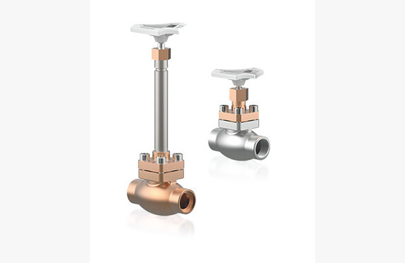
For Cryogenic Fluids
For cryogenic applications, the globe valve is made of materials that are resistant to cold, such as stainless steel. The cryo valve has an extended stem to ensure that the stem seal remains intact. The cryo valve must be clean and dry, as freezing water, for example, can damage the valve.
Globe valves are ideally suited for shut-off and control applications with cryogenic fluids. Due to their design, globe valves always incur a certain amount of flow resistance. The valve does not have an intermediate chamber where process fluid could become trapped.
Our product portfolio includes a wide range of shut-off, quick shut-off, and control globe valves for cryogenic applications from HEROSE and KÜHMEL.
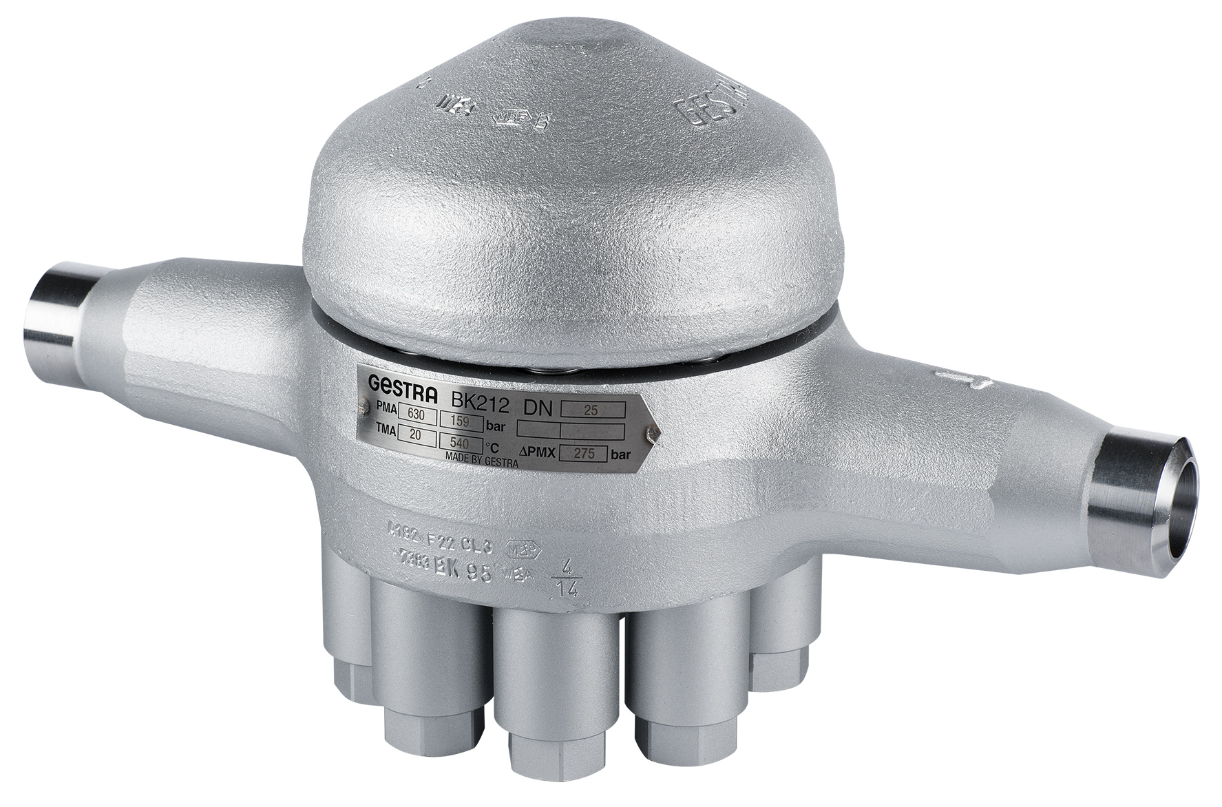
The operating principle of the bimetallic steam trap is based on a pressure/temperature-controlled bimetallic regulator. The regulator’s plates are welded together from two materials with different thermal expansion coefficients, causing them to bend when heated. The plate stack is assembled so that the bending plates are placed against each other, and the regulator closes as the pressure increases. The steam trap is adjusted so that it is fully closed just before steam flows through it, ensuring that live steam losses are 0 kg/h.
The bimetallic steam trap is particularly suitable for applications where condensate amounts are relatively small, but pressures are high.
Applications of the bi-metallic steam trap
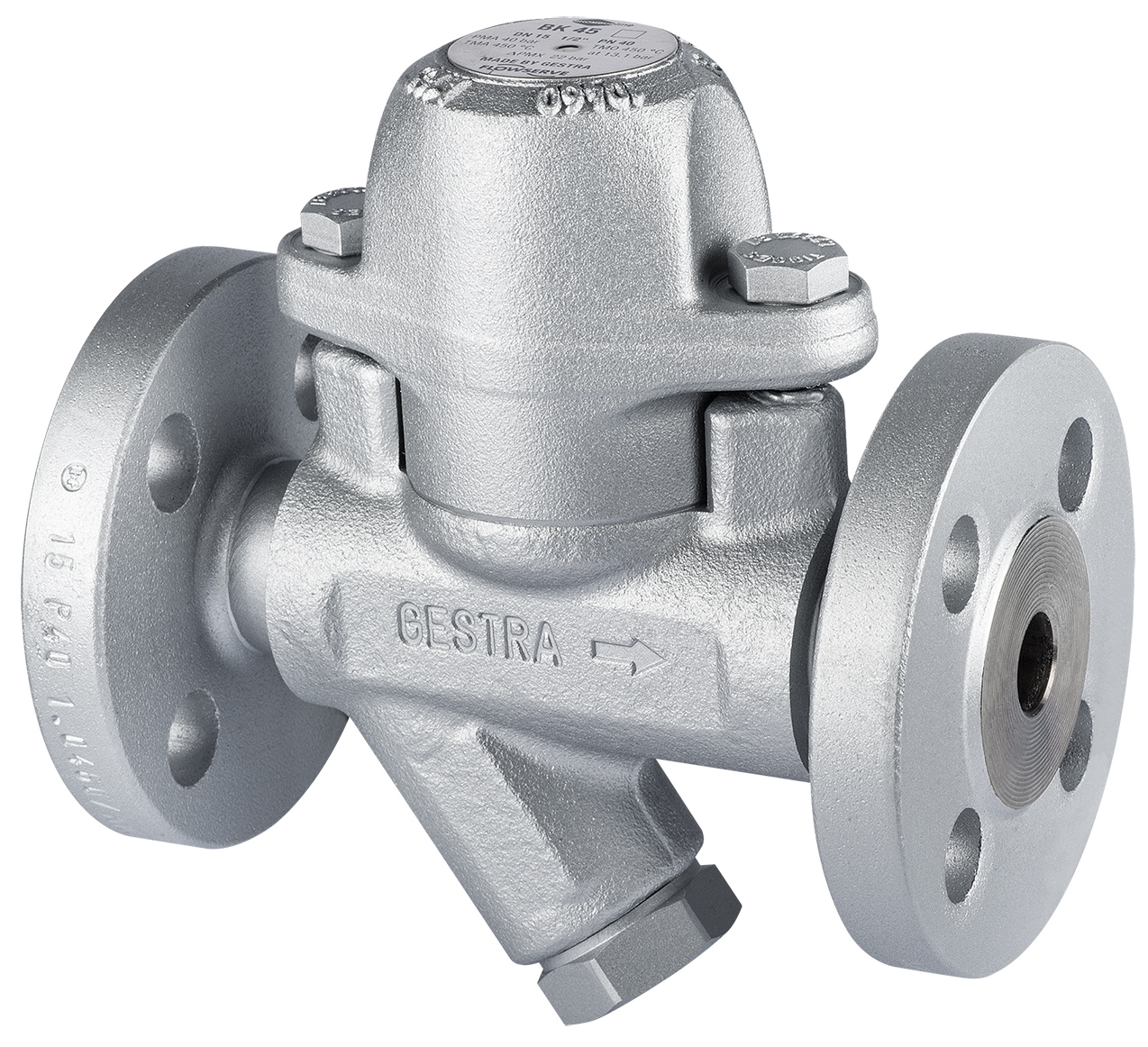
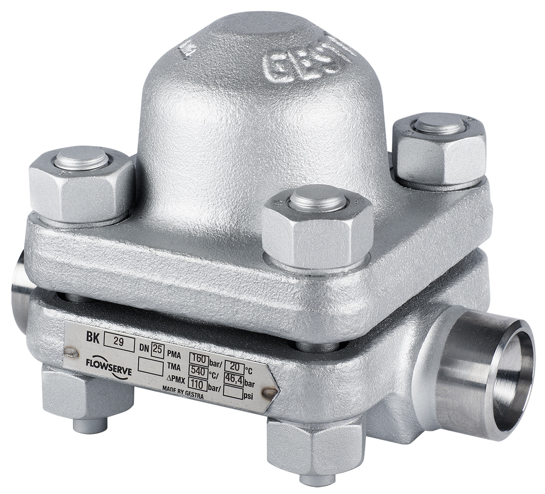
The GESTRA BK bimetallic steam trap is a robust basic steam trap. Due to its construction, it withstands superheated steam well, making it an excellent choice for power plant applications. The BK series is also a good option for applications where strong built-in backflow protection is required, especially when pressure surges affecting the trap cannot be avoided in the system design. However, it should be noted that the backflow prevention structure is not spring-loaded. The force of “pressureless” reverse flows alone is not sufficient to close the trap. In such cases, an additional check valve is recommended.
BK-series steam traps are also suitable for outdoor use.