Changeover valves

Changeover valves

FEMA S4000 kolmitieventtiili varoventtiilien vaihto
AZ-SAVA change over valve
AZ_-_UK_vaihtoventtiili
Descote_-_palkeellinen_vaihtoistukkaventtiili
FEMA_-_S4100_varoventtiilien_vaihtoistukkaventtiili
HEROSE kryogeeninen vaihtoventtiili - cryogenic change over valve

Media

Cryogenic media
Process media

Manufacturers

ARI-Armaturen
HEROSE
AZ-Armaturen
descote
FEMA

Technical specifications

Size ranges: DN 15 – 600, ASME: NPS ½“ – 24“
Pressure classes: PN 10 – 400/ Class 150 – 2500
Other: plug or poppet type
Other designations: change over valves

What is a changeover valve?

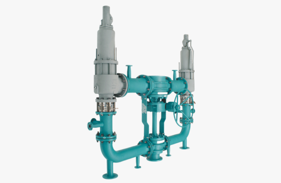
A changeover valve is a device used to divert flow from one pipe to another. The most typical changeover valve application is in connection with two safety valves, where paired safety valves are connected to the inlet and outlet pipe by changeover valves that are interconnected. In this case, one safety valve can remain in operation while the other is taken out of service by turning a hand wheel.

Selection of changeover valve

We assist in the selection and sizing of a changeover valve according to the application requirements.

For process media

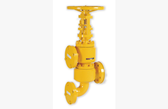
A changeover valve can be implemented in several ways. A plug-type changeover valve can be used, in which a shut-off element is located in the center of a Y-shaped body. It has seals on both sides. The valve seals one seal against the other when the other is fully open. Examples include changeover valves manufactured by ARINFEMAN and Descote. A flanged version of the Descote changeover valve is also available.

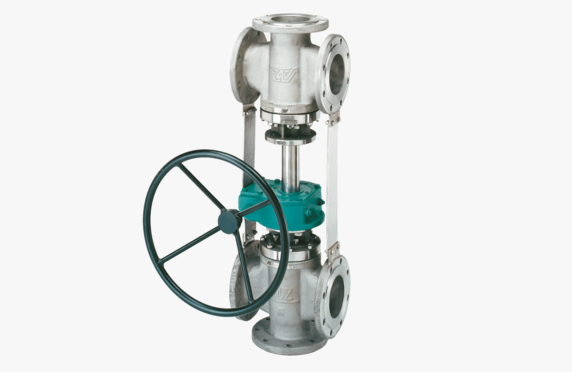
Another way to implement a changeover valve is to use a three-way plug valve. This way, the advantages of a plug valve can be utilized. For example, when dealing with challenging chemicals, one option is to use a lined three-way plug valve. In AZ’s range there is a changeover valve system that features two three-way plug valves connected to the same actuator.
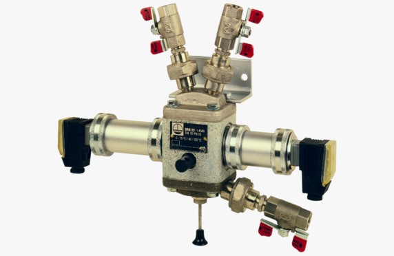
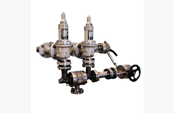
For cryogenic media

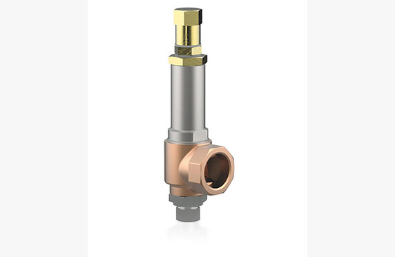
Unlike a standard ball valve, a changeover valve has at least two safety valves. Their purpose is to protect the system (e.g. a liquefied gas tank) from overpressure. Thus, the changeover valve connects two safety valves to the pressure device. In a changeover valve, there are usually two outlets but only one inlet. Changeover valves are used when the medium is a cryogenic liquefied gas, such as nitrogen.

Changeover valves are available in sizes DN 15-50. They withstand pressures up to 250 bar at temperatures from -270 °C to +400 °C. Changeover valves are mainly manufactured in stainless steel, but also in bronze and brass.

Download brochures

Process media

download

AZ SAVA Special cross-over combinations for safety valves

Lataa PDF
download

ARI-Armaturen Changeover valve 3-way Datasheet

Lataa PDF
download

AZ UK Crossover valve combinations

Lataa PDF

Process controllers

Process controllers

Media

Steam and condensate
Process media

Manufacturers

JUMO

Technical Specifications

Other designations: controllers and signal converters

What are process controllers?

In process control, various controllers are required. dTRON unit controllers are excellently suited for the regulation of pressure, temperature, and level.

Process controller selection

Our standard model is the 48×96 universal unit controller. We assist in selecting devices according to the requirements of the application. Ask our contacts for more information.

Download Brochures

download

JUMO dTRON 304 308 316 Compact Controller

Lataa PDF

Energy calculation and compensation units

Energy calculation and compensation units

Media

Steam and condensate
Natural gas, biogas and biomethane
Process media
Gas and fuel

Manufacturers

METRA Energie-Messtechnik

Technical Specifications

Supply voltage: 24 V DC or 230 V AC
Analog inputs: 2-4 pcs
PT inputs: 2 pcs
Digital inputs: 2-6 pcs
Analog outputs: 2-6 pcs
Digital outputs: 3-7 pcs
Interfaces: M-Bus, RS232, RS485, Ethernet, Profibus DP
Protocols: M-Bus, Profibus DP, Modbus (ASCII, RTU, TCP/IP)
Other designations: calculation and compensation units

What are Energy Meters and Compensation Units?

Flow meters provide their measurement results based on the pressure and temperature values set on them. In reality, however, the process values can fluctuate on both sides of the set values, and the role of the compensation units is to perform this correction. Especially in billing applications, it is important to know the flow rate very accurately. 

The calculation unit determines the values for volumetric and mass flow as well as energy. To achieve high precision, pressure- and temperature-dependent variables are continuously corrected.

Selection of Energy Meters and Compensation Units

The meters are delivered either as panel-mounted units or as ready-to-install wall-mounting enclosures. We assist with the selection of equipment according to the requirements of the application. Ask our contacts for more information.

For Steam and Condensate

METRA ERW 700 meets the calculation requirements for steam billing measurements in accordance with SFS-EN ISO 5167.

The meter comes pre-programmed with a flow calculation equation, discharge coefficients for pressure difference devices for different opening ratios and measurement methods, as well as expansion coefficients for various media.

The IAP WS IF 97 steam tables are used in the calculation.

Metal expands when heated. In billing measurements, temperature changes are taken into account by adjusting the size of the flow opening of the pressure difference device based on the temperature measurement and the pre-programmed thermal expansion coefficient.

In energy calculations, the energy of the returning condensate can also be taken into account and deducted from the total energy consumed.

For Process Fluids

METRA ERW 700 is a MID-approved unit for calculating flow and energy of district heating.

The calculation unit receives the flow rate and temperature(s). Based on the data, the consumed energy is calculated.

The specific heat capacity of a water/glycol mixture is different from that of water.

In heating/cooling systems that use a water/glycol mixture, the specific heat capacity of the medium can be programmed. The specific heat capacity of a water/glycol mixture depends on the temperature and deviates significantly from that of water.

The specific heat capacity of the medium can be programmed into the ERW 700 energy meter, ensuring the accuracy of the energy calculation.

For Gases and Liquid Fuels

The volumetric flow of liquid fuels can be converted to mass flow by taking temperature into account and calculating the density at the measured temperature.

Measurement of natural gas quantity is based on the measurement of volumetric flow. Due to compressibility, in addition to the measured volumetric flow, the prevailing pressure and temperature conditions during measurement must be considered. The measured volumetric flow of natural gas is converted to normal conditions (0 ºC and 1.01325 bar). In precise measurements, a compressibility factor is also taken into account, because natural gas behaves somewhat differently from an ideal gas, especially at higher pressures.

The calculation methods used for gaseous media are:

  • ideal gas law
  • Redlich-Kwong
  • GERG 88
  • flow correction taking temperature, pressure, and compressibility into account

The METRA ERW 700 calculation unit determines the values for volumetric and mass flow as well as energy. To achieve high precision, pressure- and temperature-dependent variables are continuously corrected.

Download Brochures

download

METRA ERW 700 Electronic Flow Computer

Lataa PDF

Ultrasonic flowmeters

Ultrasonic flowmeters

Metra ultrasonic flow meter
Metra ultrasonic flow measurement
Metra ultrasonic flow meter for hot and cold

Media

Process media
Steam and condensate

Manufacturers

Intra-Automation
METRA Energie-Messtechnik

Technical Specifications

Size classes: DN 15-1000
Pressure classes: PN 40
Materials: carbon steel
Connection ends: flanged, threaded
Temperature range: max. 200 °C
Other names: ultrasonic flow meters

What is an ultrasonic flowmeter?

Ultrasonic meters are used for measuring liquid flow.

The measurement is based on the travel time of sound in a known liquid. The ultrasonic flowmeter sends an ultrasonic signal into the pipe to be measured while also receiving the return signal. When the pipe size and the speed of sound in the flowing medium are known, the flow rate of the medium can be calculated based on the obtained signal.

Choosing an Ultrasonic Flowmeter

Ultrasonic flowmeters are also available in battery-operated form, which reduces installation costs in locations where electricity is not readily available.

Measurement is also possible from the top of the pipe.

In addition to the measurement that is introduced into the pipe, there is also measurement from the surface of the pipe. The sensors are installed at a distance from each other, as specified in the instructions for use depending on the pipe’s diameter, so that the pipe does not have to be drilled. This is also suitable for temporary verification measurements. However, the surface measurement is always performed in such a way that the pipe is full of the liquid being measured.

We assist in selecting an ultrasonic flowmeter that meets the requirements of the application. Ask our contacts for more information.

Download Brochures

download

Intra-Automation Ultrasonic Flowmeter Type IS210-S

Lataa PDF

Mass flowmeters

Mass flowmeters

Bopp & Reuther coriolis mass flow meter type fmo

Media

Process media
Gas and fuel

Manufacturers

Bopp & Reuther Messtechnik

Technical specifications

Sizes: DN15-300
Pressure: 1379 bar
Materials: stainless steel, Hastelloy, tantalite, Duplex
Accuracy: ±0.15%
Process temperature: -200 °C…+400 °C
Special features: suitable for high-pressure applications, measurement of corrosive liquids, available with various electronic transmitters
Other designations: mass flow meters

What is a mass flowmeter?

In mass flowmeters, the flow passes through a vibrating measurement tube. Due to the effect of the mass flow, the vibration of the tube changes in such a way that a phase difference arises between the beginning and end sections. The magnitude of the phase difference is proportional to the mass flow; the larger the mass flow, the larger the phase difference.

Mass flowmeter selection

Our range includes mass flowmeters from Bopp & Reuther.

Mass flow measurement is suitable for various liquid media. The meters are available with a separate electronics/counting unit.

We assist in selecting a mass flowmeter that meets the requirements of the application. Ask our contacts for more information.

Download Brochures

download

Bopp u0026 Reuther FMO Coriolis Transducer

Lataa PDF

Magnetic flowmeters

Magnetic flowmeters

Media

Steam and condensate
Process media

Manufacturers

Bopp & Reuther Messtechnik

Technical Specifications

Size ranges: DN 15-2000
Pressure classes: PN 6-40
Body materials: carbon steel, stainless steel, Hastelloy
Electrode materials: Hastelloy, platinum-coated stainless steel, titanium
Lining: soft rubber, hard rubber, PTFE/PFA
Accuracy: ±0.25% of the measured value, ±0.1% of the full-scale value
Special features: empty pipe detection, third grounding electrode optional, bidirectional measurement, direct output 4–20 mA, pulse output, Modbus (RTU & ASCII), battery-powered solutions available
Other names: magnetic flow meter

What is a Magnetic flowmeter?

Magnetic flowmeters are used for electrically conductive liquids with a conductivity of at least 5 µs/cm.

The measurement is based on electromagnetic induction. Electromagnets create a magnetic field; when an electrically conductive medium flows through the magnetic field, it induces a voltage. The voltage increases as the flow increases according to the following formula:

U = B*I*V
U = induced voltage
B = magnetic flux density
I = distance between the measuring electrodes
V = flow velocity of the medium

Selection of the magnetic flowmeter

In addition to a wide measurement range, magnetic flowmeters are a relatively cost-effective method for liquids.

The measuring tube is normally lined with rubber or Teflon, but it is also available without lining for corrosive applications.

We assist in selecting a remote control device that meets the requirements of the application. Ask our contacts for more information.

Download Brochures

download

Bopp u0026 Reuther SpiraMAG Electromagnetic Flowmeter

Lataa PDF

Differential pressure-based flow measurement

Differential pressure-based flow measurement

Paine-erovirtausmittari EWZ_1271
Metra EDZ_1501 paine-eromittari - differential pressure meter

Media

Steam and condensate
Process media

Manufacturers

Bopp & Reuther Messtechnik
METRA Energie-Messtechnik

Technical specifications

Sizes: DN 15-1000
Pressure classes: PN 10-320
Materials: carbon steel, acid-resistant steel, high-strength steels
Other names: differential pressure-based measurement

What is differential pressure-based flow measurement?

When the medium is constricted, the pressure difference is increased. By measuring this pressure difference and relating it to the density of the medium and the pipe size used, the flow rate can be calculated using the pressure difference.

The measurement is suitable for liquids, gases, and vapours.

Selection of the differential pressure flow meter

Differential pressure measurement is an old, comparatively simple method of flow measurement.

Our BOPP&REUTHER and METRA differential pressure devices can be delivered either as separate installations or compactly with the differential pressure transmitter installed directly in the measurement run.

In billing applications, measurement is primarily carried out using methods in accordance with the standard SFS EN 5167.

The measurement methods in accordance with the SFS EN 5167 standard are:

  • orifice plate (constriction plate)
  • flow nozzle (ISA-1932)
  • Venturi nozzle
  • Venturi tubes

The standard specifies:

  • the structure and manufacturing method of the pressure device
  • the flow rate calculation equation
  • the discharge coefficients for differential pressure devices for various orifice ratios and measurement methods
  • the expansion factor for gaseous media
  • the straight-run lengths before and after the differential pressure device

In few processes are pressure and temperature constant. For this reason, the medium’s density ρ must be compensated based on temperature and pressure. Compensation can be done either directly in the differential pressure transmitter or by using a separate compensation unit.

Metal expands when heated. In billing applications, temperature changes are taken into account by adjusting the size of the differential pressure meter’s flow opening based on temperature measurements and a pre-programmed thermal expansion coefficient.

Optionally, METRA’s differential pressure transmitters can be equipped with an automatic zero point calibration module. This significantly prolongs the maintenance of measurement accuracy and reduces the need for device calibration.

Download brochures

download

METRA EDZ / EWZ 110.1 / 117.1 Flow/Energy Meter

Lataa PDF
download

METRA EDZ/EWZ 150.1 and EDZ/EWZ 157.1 Flow/Energy Meter for Technical Gases

Lataa PDF
download

METRA EDZ/EWZ 1×0.1 and EDZ/EWZ 1×7.1 Flow/Energy Meter for Vapours, Liquids and Technical Gases

Lataa PDF

PD meters

PD meters

PD-mittari VAF j5015
vafmeter

Media

Process media
Gas and fuel

Manufacturers

Bopp & Reuther Messtechnik
VAF Instruments

Technical specifications

Sizes: DN 10-400
Pressure classes: PN 10-100
Materials: GGG 40.3, C-steel, AISI 316, PVDF
Measurement range: 1.8 l/h – 1 440 m3/h
Accuracy: ±0.1-0.5 %
Other designations: PD flow measurement

What is a PD meter?

PD meters are used to measure various liquids. They operate on the displacement principle, meaning that with one full rotation a certain volume passes through the meter.

Selecting a PD meter

Viscosities can range from those of liquid gases to the properties of bitumen. If a liquid can be pumped, it can also be measured.

The meters are highly accurate and are therefore well suited for dosing, measuring additives and oil consumption, or for billing purposes. The range includes various display devices, counters, and signal converters.

Other media can include acids, ethylene, propylene.

Download brochures

download

VAF PT2 LoFlow MidFlow Sliding Vane Flowmeters

Lataa PDF
download

VAF MidFlow HiFlow Sliding Vane Flowmeters

Lataa PDF
download

Bopp Reuther OI Oval Wheel Meter

Lataa PDF
download

Bopp Reuther Flowal Plus OR OF Oval Wheel Meter

Lataa PDF

Vortex flowmeters

Vortex flowmeters

Media

Steam and condensate
Process media

Manufacturers

Bopp & Reuther Messtechnik

Technical specifications

Sizes: DN 15-300
Pressure classes: PN 16-100
Materials: AISI 316, steel, hastelloy
Temperatures: -40 °C…+400 °C
Accuracy: ±0.6 %
Other names: vortex flow meter

What is a vortex flowmeter?

Vortex flowmeters have a bluff body that causes vortices to form alternately on both sides of the obstruction. The frequency of the vortices is proportional to the flow velocity. The volumetric flow rate can be calculated from the flow velocity when the pipe diameter is known.

The advantage of vortex measurement is its simplicity, versatility, and affordability. It is suitable for many applications.

Selection of vortex flowmeter

Vortex meters are suitable for measuring low-viscosity liquids and gases.

The electronics can also be supplied separately, allowing the meter to be used at high temperatures. Both flange-mounted and between-flange models are available.

We assist in selecting a vortex flowmeter that meets your application requirements. Contact our representatives for more information.

Download brochures

download

Bopp & Reuther Vortex Meter VTX3 datasheet

Lataa PDF

Turbidity monitoring

Turbidity monitoring

GESTRA ORT6-02-5MB2 Turbidity Detector
Öljyn ja sameuden mittaus - turbidity measurement

Media

Process media
Steam and condensate

Manufacturers

GESTRA

Technical specifications

Pressure and temperature: PN 10, 120 °C
Materials: GG-25, 1.4580
Measurement range: 0-25 ppm
Operating voltage: 230 V, 48-62 Hz, optionally 110 V
Output: 0/4-20 mA
Other names: turbidity monitoring

What is turbidity monitoring?

The measurement of oil and turbidity is based on an in-line intermediate sample drawn from the process, which is passed through the meter and then returned to the process. A light signal is passed through the medium, with its refraction in a clean medium known.

Selection of turbidity monitoring devices

For example, in condensing systems the meter checks the purity of the condensate. In several industrial processes where product tanks are heated with steam, there is a risk that if the heating coils burst, a foreign substance such as oil flows into the condensate system. Upon detecting a change in the purity of the condensate, the GESTRA OR oil and turbidity sensor immediately sends information to the control room and triggers, for example, a 3-way valve in the line to divert the dirty condensate to a reserve container.

This ensures that information about an abnormal condition is received quickly, and the oily condensate does not contaminate the entire condensate system.

GESTRA OR 52 is designed for continuous monitoring of turbidity, emulsified oil, and fat content in liquids.

Applications include monitoring the oil content in condensate from steam boiler plants as well as overseeing sand filters, reverse osmosis, and mineral removal in water treatment plants. Other applications include wastewater treatment plants and the beverage industry, among others.

We assist in selecting turbidity monitoring devices that meet the requirements of your application. Contact our representatives for more information.

Download brochures

download

GESTRA OR52-5 OR52-6 Turbiscope Datasheet

Lataa PDF