Teflon lined butterfly valves

Teflon lined butterfly valves

Garlock teflonvuorattu läppäventtiili - teflon lined butterfly valve
Garlock teflon butterfly valve
Garlock-läppäventtiili

Media

Process media

Manufacturers

Garlock

Technical specifications

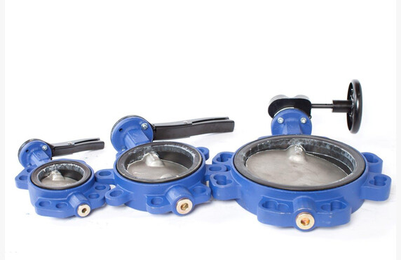
Sizes: DN 50–600, ASME
Pressure Classes: PN 10–16, ANSI 150#
Operating Temperatures: -40 °C…+200 °C (UHMWPE lining 85 °C)
Operating Pressures: 1 mbar–16 bar
Flanged Connections: installed between flanges, lug type end flange
Other: FDA approval (white PTFE and antistatic lining), TA-Luft highest class DIN15848, A – 35 kV spark test, MTBF classification EN 61508 SIL2, non-slam baffle according to standard EN 731-3, PED 2014/68/EU, ATEX
Other Names: teflon lined butterfly valve

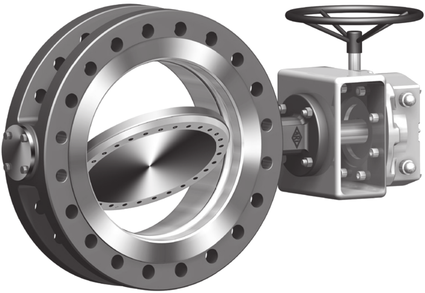
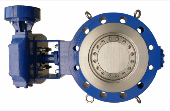
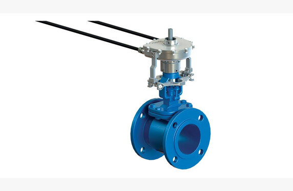
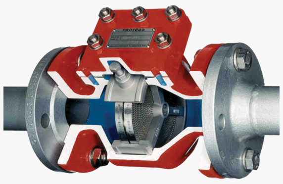
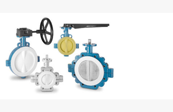
What is a teflon lined butterfly valve?

Teflon, or PTFE-lined butterfly valves, are designed for the reliable control of corrosive, toxic, abrasive, and explosive media.

Selection of a teflon lined butterfly valve

We assist in selecting and sizing a butterfly valve that meets the requirements of your application.

Garlock valves are known, among others, in the chemical, petrochemical, process, food industries and many other industrial sectors for their quality, performance, and reliable operation even in challenging conditions. Garlock butterfly valves are manufactured to meet the requirements of TA-Luft and the FDA, and they are SIL 2 certified according to the EN 61508 standard.

Garlock butterfly valves use PTFE (Polytetrafluoroethylene) lining due to its excellent chemical resistance. In Garlock’s manufacturing facility in Neuss, Germany, an isostatic casting process is used for the valve lining (the granules are compressed uniformly from all sides) to ensure product quality and durability.

Garlock GmbH Neuss – Germany is certified to EN ISO 9001:2008 and EN ISO 14001:2004.

Watch our YouTube overview of PTFE butterfly valves.

Garlock Butterfly Valve Product Lines
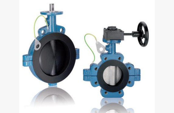
GAR-SEAL

GAR-SEAL butterfly valves are widely used in various applications where corrosive, abrasive, or toxic media need to be controlled reliably. GAR-SEAL is used to throttle or shut off flow in facilities such as chemical, petrochemical, and paper manufacturing plants. The use of GAR-SEAL butterfly valves improves operational reliability and reduces maintenance costs.
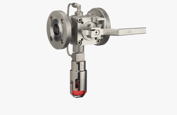
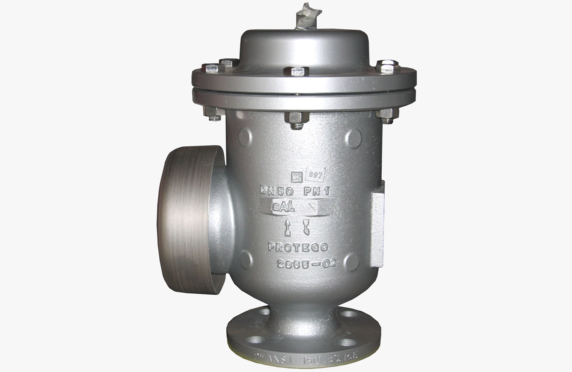
MOBILE-SEAL

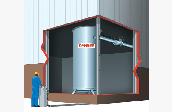
MOBILE-SEAL butterfly valves are used in tank vehicles, railcars, silos, and other transport and storage tanks where specialized safety requirements are needed. MOBILE-SEAL valves are EN 14432 approved.
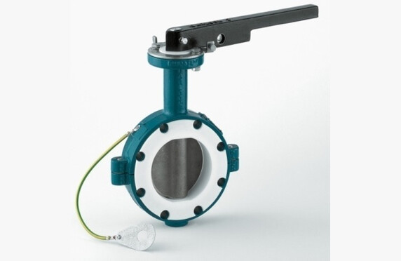
SAFETY-SEAL

SAFETY-SEAL butterfly valves are commonly used in applications where electrostatic charges must not be generated. This is achieved with conductive lining and grounding.
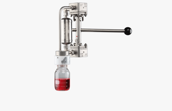
STERILE-SEAL

STERILE-SEAL butterfly valves are used in sterile processes, for example in the pharmaceutical and food industries. A special feature of this valve is its external sterilization readiness. Steam can be used to sterilize the “dead” zones of the valve without the steam coming into contact with the process medium.
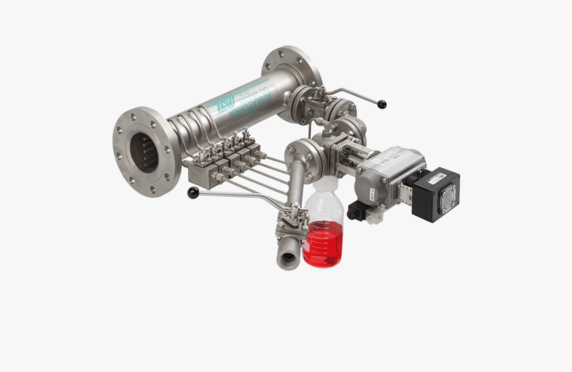
TOXI-SEAL

TOXI-SEAL butterfly valves are used to control odor emissions in chemical, hazardous, or toxic applications where the release of a vaporizing medium into the environment must be prevented. The Garlock TOXI-SEAL butterfly valve is suitable for applications due to its leak-proof chamber and piston pressure seal.
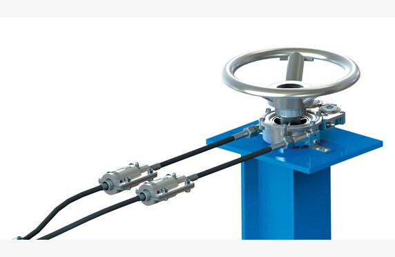
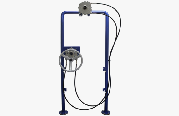
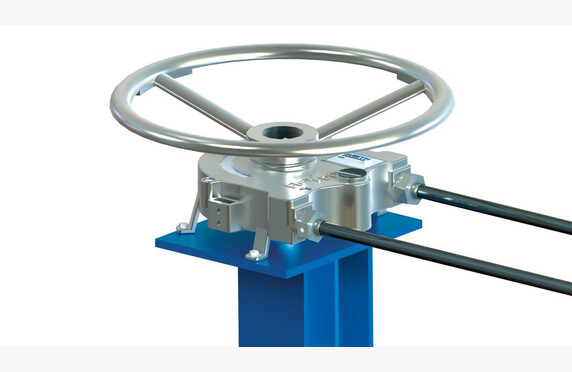
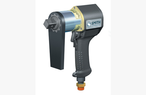
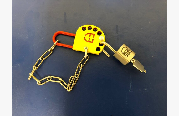
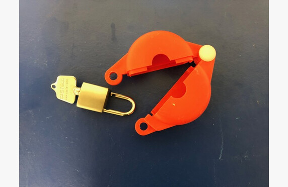
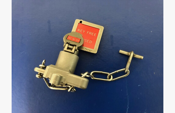
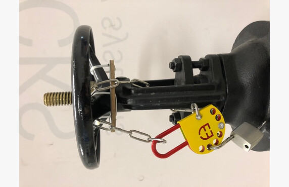
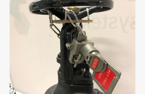
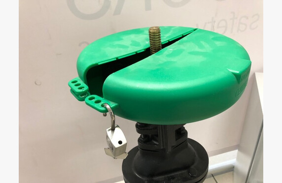
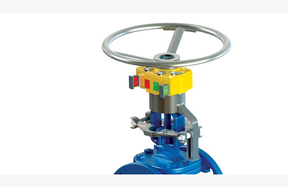
VALVE ACCESSORIES

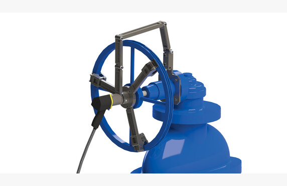
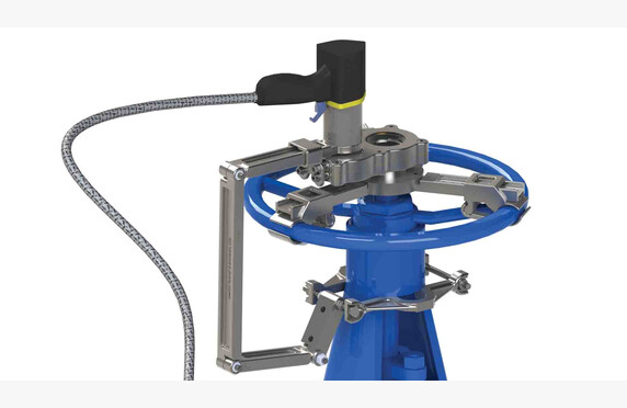
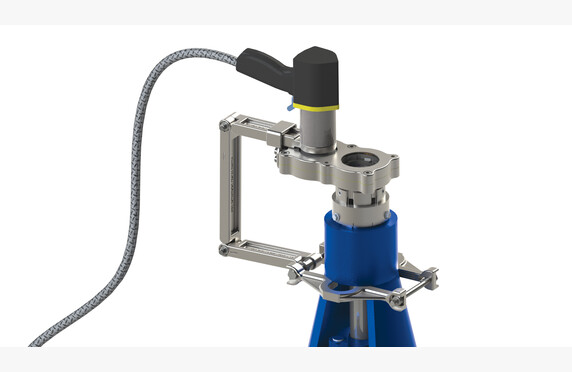
Garlock also offers a full range of valve accessories, such as special locking handles and gearboxes. The automation sector offering is comprehensive, including valve installation kits, actuators, limit switch devices, and valve positioners.

Download Brochures

download

Garlock Butterfly Valves

Lataa PDF

Metal seated butterfly valves

Metal seated butterfly valves

ARI Zetrix butterfly valve
TU-A-I-läppäventtiili 1 Armatury Group L32 8
Kolmoisepakeskeinen läppäventtiili kuva

Media

Steam and condensate
Gas and fuel
Natural gas, biogas and biomethane
Process media
LPG
Cryogenic media

Manufacturers

ABO valve
OMB Valves
R.T. Valvole
ARMATURY Group
ARI-Armaturen

Technical specifications

Size classes: DN 80–1200, NPS 3”–24”
Pressure classes: PN 10–100, ANSI 150/300
Temperature range: -196 °C…450 °C
Materials: steel, stainless and acid-resistant steel, special materials
Connection ends: between flanges, flanged, welded, lug type
Other names: metal seated butterfly valve

What is a metal seated butterfly valve?

In metal seated butterfly valves, the sealing surface between the disc and the body is, as the name suggests, metal.

Because the pressure and especially temperature resistance properties of metal seated butterfly valves are clearly superior to those with a rubber seat, their range of applications is also significantly broader. The characteristics of a metal seated butterfly valve can be influenced by the degree of eccentricity.

Eccentricity of the butterfly valve

In an eccentric butterfly valve, the disc rotates off-center, as the name suggests. This achieves a higher surface pressure between the disc and the seal as well as a rapid decrease in surface pressure and friction when opening the valve. In simple terms, eccentricity results in higher tightness and a lower opening torque. With triple eccentricity, significantly higher surface pressure and sealing are achieved.

  1. The first degree of eccentricity arises from the fact that the shaft is positioned behind the disc.
  2. The second degree of eccentricity is achieved by placing the shaft to the side of the disc’s centerline.
  3. The third degree of eccentricity is implemented by machining the sealing surface of either the disc or the body in an eccentric manner. Machining both achieves the aforementioned reduction in friction.

Typical applications for eccentric butterfly valves include: oil and gas production and processing, petrochemical industry, chemical industry, power plants, district heating, solar power plants, pulp and paper industry, steel industry, and sugar industry.

Choosing metal seated butterfly valves

We assist in selecting and sizing a butterfly valve that meets the requirements of your application. The installation options include between-flange, flanged, lug type (end flange) or welded models. Our triple eccentric butterfly valves are standardly of sealing class A, according to the EN 12266-1 standard.

The available ARI-ZETRIX- and RT Valves butterfly valves can be equipped with pneumatic or electric actuators.

For steam, condensate and process fluids

ARI-ZETRIX®, RT and AG offer triple eccentric and Högfors double eccentric valves. The metal seated butterfly valve is not only an on/off valve, but it is also suitable for specialized control applications.

Watch the YouTube video  about Ari Armaturen’s emergency shutdown valve.

For liquid fuels

For fuel applications, Fire-Safe valves are available, which have been fire safety tested according to the ISO 10497 standard or API 607 standard. They are also ATEX certified.

For the seals of the stem, certificates according to ISO 15848-1 or TA-Luft are available.

For cryogenic fluids

In cryogenic lines, high performance models, i.e. triple eccentric butterfly valves, are used.

The triple eccentric butterfly valve performs better in demanding conditions than simpler butterfly valves. In large sizes, the butterfly valve is lighter than other types of valves.

The butterfly valve can be of a top-entry design, meaning that the valve is installed in the pipe by welding, but it has a top hatch to ensure maintainability.

The German company HEROSE manufactures metal seated triple eccentric, that is, triple-offset butterfly valves suitable for cryogenic conditions.

Download brochures

Steam and Condensate

download

ARI-Armaturen ZEDOX Double Offset Butterfly Valve – Thread Connection

Lataa PDF
download

ARI-Armaturen ZEDOX Double Offset Butterfly Valve – Double Flanged

Lataa PDF
download

ARI-Armaturen ZEDOX Double Offset Butterfly Valve – Butt Weld Ended

Lataa PDF
download

ARI-Armaturen ZEDOX Double Offset Butterfly Valve – Wafer Type

Lataa PDF
download

ARI-Armaturen ZETRIX Triple Offset Butterfly Valves

Lataa PDF

Process Fluids

download

ARMATURY Group Type L32.8 Triple-Eccentric Butterfly Valves

Lataa PDF
download

ARI-Armaturen ZEDOX Double Offset Butterfly Valve – Thread Connection

Lataa PDF
download

ARI-Armaturen ZEDOX Double Offset Butterfly Valve – Double Flanged

Lataa PDF
download

ARI-Armaturen ZEDOX Double Offset Butterfly Valve – Butt Weld Ended

Lataa PDF
download

ARI-Armaturen ZEDOX Double Offset Butterfly Valve – Wafer Type

Lataa PDF
download

ARI-Armaturen ZETRIX Triple Offset Butterfly Valves

Lataa PDF

Liquid Fuels

download

ARI-Armaturen ZETRIX Tripple Offset Butterfly Valves

Lataa PDF
download

R.T. Valvole Triple Offset Butterfly Valves

Lataa PDF

Rubber lined butterfly valves

Rubber lined butterfly valves

ARI-Armaturen kumivuorattu läppäventtiili - rubber lined butterfly valve
kumivuoratut läppäventtiilit

Media

Process media

Manufacturers

ARI-Armaturen
ABO valve

Technical specifications

Sizes: DN 40-2000
Pressure Classes: PN 10-40
Body Materials: GG-25, GGG 40, GS-C 25, AISI 316
Disc Materials: AISI 316, GGG 40, aluminum bronze
Lining: EPDM, heat-resistant EPDM, NBR, Viton
Flange Connections: between flanges, flanged, end flange model (lug type)
Other Names: rubber lined butterfly valve

What is a rubber lined butterfly valve?

Rubber-lined butterfly valves are suitable as shut-off valves in both large and small low-pressure water pipelines. They are lightweight, easy to install, user-friendly, and tight.

The installation options include a wafer type (installed between flanges), flanged, or the so-called end flange model (lug type) equipped with threaded ears.

Selection of a rubber lined butterfly valve

We assist in the selection and sizing of the butterfly valve according to the application requirements.

Typical media include process cooling water, seawater, dirty water, clean water, and fresh water. A suitable material combination is available for each medium application. Typically, the valve body is made of cast or ductile iron with graphite, and the body lining is selected based on the medium. We stock valves lined with EPDM and NBR.

Valves can be equipped with pneumatic or electric actuators. They can also be installed underground and operated remotely from the surface using an extension arm.

Large butterfly valves must be installed in the pipeline so that the valve handle is horizontal.

Download Brochures

download

ARI-Armaturen ZESA, GESA, THEA Butterfly valves

Lataa PDF
download

ARI-Armaturen ZESA EA, GESA EA Butterfly valves

Lataa PDF
download

ARI-Armaturen ZIVA-Z, ZIVA-G Butterfly valves

Lataa PDF

Control centers

Control centers

Media

Steam and condensate
Process media

Manufacturers

Konwell

Technical specifications

Other names: control centre

Design and selections of the control center

We design, size and manufacture control centers according to the customer’s needs.

Control centers for control valves and heat exchanger units are designed on a case-by-case basis and delivered with project-specific control diagrams. For the customer, this means flexibility and fast delivery times.

Control centers intended for the control of large machinery systems and equipment are manufactured according to the customer’s own electrical plans.

At the request of the customer, we also perform the necessary field installations, cabling and connections.

Ask our contact persons for more information.

Sampling

Sampling

AZ-Armaturen contiflow näytteenottoventtiili - sampling valve
AZ_produkt-probenahme-sampling-sic
AZ vario sampling valve - näytteenottoventtiili
AZ-Armaturen sampling valve
AZ-Armaturen gsp
AZ-Armaturen LG-SP

Media

Gas and fuel
Process media

Manufacturers

AZ-Armaturen

Technical details

Sizes: DN 15-100, ASME 1/2
Pressure classes: PN 10-40, ANSI 150#-300#
PT range: -40 < T < 230°C, vacuum 10-8 mbar
Body materials: 1.0619 (WCB), 1.4408 (CF8M), 1.4308 (CF8), cold resistant 1.1138 (LCC), also special materials
Plug materials: 1.4408 (CF8M), 1.4308 (CF8), also special materials
Features: closed system, pressureless sampling, simple and safe operation, environment is not exposed to process fluid during sampling, predetermined sampling volume, Ta-luft 2002 well-tested valves
Other: the complete system can be customized according to the application’s requirements
Other names: sampling valve, sampling valve

What is a sampling valve?

Sampling valves differ in structure and operating principle, but they all share the same goal and key features. A sampling valve takes a sample from the flow neatly and safely without disturbing the process.

Choosing a sampling valve

A good sampling valve is easy to use. It enables safe, pressureless sampling without exposing the environment or operator to the process fluid. The sample volume can be predetermined, so the desired amount always goes into the sample container.

Sampling does not disrupt the process itself; the system flow is not interrupted during sample collection. The sample must be a fresh portion of the process fluid flowing in the pipe. A good sampling valve does not have a “dead” volume, as is the case with a conventional ball valve. If a conventional ball valve were used for sampling, the dead volume would contain old process fluid and the sample would not correspond to the process fluid in the pipe at the time of sampling.

Our solutions cover AZ-Armaturen sampling solutions for solid, liquid and gaseous process fluids for various industrial needs. The range also includes products for sampling extremely aggressive process fluids.

We assist in selecting and customizing a sampling solution that meets the requirements of the application. Please ask our contacts for more information.

Download brochures

download

AZ-Armaturen Contiflow

Lataa PDF
download

AZ-Armaturen gb S3 SAMPLING PPV DS

Lataa PDF
download

AZ-Armaturen Vario

Lataa PDF
download

AZ-Armaturen Sampling SIC

Lataa PDF
download

AZ-Armaturen Sampling for Liquids

Lataa PDF
download

AZ-Armaturen GSP

Lataa PDF

Valve remote control equipment

Valve remote control equipment

flexidrive remote cable drive valve operator - kaukokäyttölaite
flexidrive_sv_operointipiste
Venttiilien_kaukokayttolaitteet
flexidrive
flexidrive_operointiasema
flexidrive remote valve operator
flexidrive_venttiiliasema
flexidrive_sv_osoittimet

Media

Process media
Cryogenic media
Gas and fuel
Steam and condensate

Manufacturers

Smith Flow Control
Sofis

Technical specifications

Other: operating point up to 60 meters from the valve, allows cable bends, fire-resistant cable
Alternate names: remote cable drive valve operator

What is a valve remote control device?

With a remote control device, valves located in dangerous or otherwise difficult-to-access places can be easily operated. The remote control device consists of two gear-driven operating units and a cable running between them. One operating unit is installed on top of the valve to be operated and the other where the valve is intended to be controlled from.

The remote control device is suitable for all valve models, whether screw or hand lever operated, and it is easy to install afterwards on an existing valve.

Selecting a valve remote control device

When constructing systems, valves cannot always be placed in locations optimal for operation; they are sometimes located on high pipe bridges, in low, narrow piping tunnels, or in areas where environmental conditions pose their own challenges to the normal operation of the valve.

If a valve placed in a challenging location is operated infrequently, its automation may be too costly. It is precisely for such cases that Smith Flow Control’s FlexiDrive manual remote control device, part of the Sofis Group, has been designed.

Thanks to the flexible cable, the operating point can be positioned up to 60 meters away from the valve itself. FlexiDrive installation sites may also include turns and bends of up to 720 degrees, which are not possible with chain wheels and extension bars.

In addition to the aforementioned pipe bridges, installations have been made on valves mounted on the walls of large terminal tanks and in the confined spaces of icebreakers. Installations have also been carried out, for example, in a nuclear power plant, where the operated valves are on the so-called radiation side and the operation is desired to be brought to a safe area.

We help select a remote control device that meets the requirements of the application. Ask our contacts for more information.

Download brochures

download

Sofis FlexiDrive remote operator

Lataa PDF
download

Smith Flow Control Flexi-Drive

Lataa PDF

Portable valve actuators

Portable valve actuators

easidrive venttiilin operointityökalu - valve remote control
easidrive käsipöyrä pystyssä
sofis easidrive ilman käsipyörää
TU-A-I-Varo-4_operointityokalu
Sofis EasiDrive

Media

LPG
Steam and condensate
Cryogenic media
Process media
Gas and fuel
Natural gas, biogas and biomethane

Manufacturers

Sofis
Smith Flow Control

Technical specifications

Other names: easy drive, EasiDrive, remote valve operator, valve operating tool

What is a portable valve actuator?

Heavy valves used in various industrial processes pose a challenge, especially from a safety perspective. Different types of turning levers are used, and unfortunately, minor – and sometimes even major – workplace accidents occur. Not to mention that operating a large wedge-slip valve from one extreme position to another is quite strenuous. Valve operating tools can make valve operation easier and safer.

Choosing a portable valve actuator

A new valve might be light, but over time it becomes heavier and heavier. Lubrication no longer helps, and replacement or automation is expensive.

We have good experience performing valve open and close operations using the operating tool.

There are two options available. In both cases, for example, compressed air is used as the power source, which easily provides the required torque.

See presentations for both options.

The advantage of the EasiDrive featured in the video is that it is a small, handy tool. It features a fixed platform that is mounted on top of any existing valve. You can see various options in the photographs above. The tool—the gun—is placed on this platform, and with a press of a button, you can operate the valve to open or close. The device has its own adjustment for the applied torque.

The advantage of the Power Wrench featured in the video is that no fixed platform for the tool is required; instead, as the video shows, the platform can be easily mounted onto the existing valve handwheel.

If you are interested in testing the device at your facility, we are happy to perform a demonstration. We have both tools in stock.

Download Brochures

download

Sofis EasiDrive-operointityökalu

Lataa PDF
download

Sofis EasiDrive portable actuator

Lataa PDF
download

Smith Flow Control easy drive -operointitykalu

Lataa PDF

Valve lockout systems

Valve lockout systems

Valve lock - venttiililukko
Valve safety lock - venttiilin turvalukitus
venttiilin turvalukitus
turvalukitus
venttiilin lukko
lockout tagout
interlock turvalukko asennettuna - valve interlock
interlock avainkaappi - key storage
Valve security interlock
interlock_viritys
yleiskuva_turvalukitukset

Media

Natural gas, biogas and biomethane
Gas and fuel
LPG
Steam and condensate
Cryogenic media
Process media

Manufacturers

Sofis
Netherlocks
Smith Flow Control

Technical Specifications

Other designations: Lockout, Tagout, Master lock, valve safety locks

What is a valve lockout system?

Work safety is fundamentally linked to the safe operation of processes. According to statistics, numerous industrial accidents are caused by so‐called human errors in operation. Either the wrong valve is operated, or it is assumed that the process valves are in a different position than they actually are.

To prevent such human operational errors, a program was developed in the United States by The Occupational Safety and Health Administration (OSHA) called The Control of Hazardous Energy Source Standard, which now serves as an international standard for managing accident risks. In Finland, the concept known as Lockout/Tagout has become a useful term, which simply means reliably disconnecting the energy supply (Lockout) and marking the disconnection (Tagout).

At its simplest, incorrect operation can be attempted to be prevented by a “do not turn” sign, or by tying something to the valve that obstructs, or at least slows down, operation—a rope or some other contraption. However, safety locking is only considered achieved when operation is prevented by some type of lock. On this site, we present various options for implementing safety locks, ranging from simple chain locks to advanced Interlock safety locks, which can also create sequential orders for operating multiple valves.

Selection of a valve lockout system

The following flowchart helps determine whether a lock is needed at all for the target, and if so, what kind. For example, if it concerns a safety device, such as a dual-redundant safety valve, Tukes has determined that a chain lock does not eliminate human operational errors, but that an Interlock sequence is required at the site. The same applies if it is important that the valve is definitely 100% open or closed after operation.

By “sequence” it is meant that several valves are operated in a planned order one after the other. In these cases as well, the Interlock safety lock eliminates “human errors”.

Selection of Valve Safety Lock

In our blog post Valve Safety Lock Options, the differences between these various locking options are explained in further detail. The possibilities of key management systems are explained in a separate blog post.

Simple Safety Locks

Various locking cable locks or protective covers that lock hand wheels are simple and cost-effective ways to perform valve LOTO (Lockout/Tagout) safety locking. Lockout/Tagout means reliably disconnecting the energy supply (Lockout) and marking the disconnection (Tagout).

From Cable Lock to Hand Wheel and Handle Protective Cover

A Lockout/Tagout (LOTO) lock can be created by tying the valve’s hand wheel with a cable so that its operation becomes impossible. At its simplest, it can be implemented using CarSeal straps designed for industrial use, which operate on the principle of a cable tie and are therefore disposable.

A more advanced version is various cable locks that are secured with a mechanical key lock. The cables can be either fixed-length or adjustable. Multiple locks can be attached to a single cable, which can, for example, be color-coded to ensure that the lock is secured by two or more persons. The keys can be personalized so that a particular department or even an individual has their own lock, with which they lock and are the only one who can remove it.

The possibilities for key codings are unlimited.

Another option for performing the lock is to prevent the valve operation by protecting and mechanically locking the hand wheel or handle with a protective cover. In this case, the key system works the same as in chain locks.

Not only valves, but various other targets, such as electrical systems, can be locked with mechanical locks.

For managing keys and locks, our software offers various storage cabinets. An essential part of the LOTO system is the marking (Tagout) that must be performed in connection with the locks (Lockout), so that incoming personnel observe and understand that a part of the process has been intentionally isolated from normal operation.

These marking supplies are also available in our product range.

Valve interlocks

A more advanced method to lock a valve is the interlock. It eliminates the risks of manual operation by enforcing a pre-planned operational order, thereby ensuring the safety of both the process and the worker. The manufacturing of Interlock safety locks is handled by process safety equipment manufacturer Sofis.

How does the interlock work?

In a safety lock, a locking device is installed over either an existing or a new valve, which operates with a separate key. The key is typically stored in a dedicated key cabinet in the production facility’s control room. Without the key, the safety lock cannot be operated.

The keys for safety locks are typically marked with both text identifiers and color codes. The color code provides an at-a-glance indication of whether the valves in the process are in their default or abnormal positions.

It is even possible to automate the key management system. This is explained in more detail in our blog post.

See the operation of the locking device and an example of color coding in this video.

System locking options – sequences

Operations in processes often require that multiple valves be operated consecutively. In such situations, the strengths of interlock safety locks come to the forefront. It should be noted that, for example, TUKES has begun to require that in tanks with several safety valves, it must be ensured that not all backup devices are accidentally closed at the same time. This assurance is easily achieved with an Interlock locking system.

See a sequence example in the video.

Installation on existing valves

The Interlock safety lock is suitable for all valve models – including actuator-controlled valves – and for all nominal sizes. It is also easy to install retroactively. In such cases, our installers will measure the end-to-end dimensions of the old valve, upon which the factory manufactures an adapter piece to be placed between the locking device and the valve. Our installation team has undergone official factory training, so the installation and adjustment of safety locks is handled with ease.

We have also held a webinar on interlock safety locks, which you can watch below.

Download Brochures

download

Sofis SFC Interlocks

Lataa PDF

Flame arresters

Flame arresters

PROTEGO flame arrester - liekinestin
liekinestinlevy

Media

Process media
Natural gas, biogas and biomethane

Manufacturers

PROTEGO

Technical specifications

Size ranges: DN 15-1600
Materials: GGG 40, GS-C 25, AISI 316, Hastelloy
Connections: threaded, flanged
Other designations: flame trap, deflagration flame arrester, flame arrester, flame arrestor, flame damper

What is a Flame Arrester?

A flame arrester (eng. flame arrester) itself cannot prevent ignition from occurring, but when properly selected and installed, it can prevent the flame from entering parts of the piping where it is not wanted. The device’s nickname, flame trap, is quite descriptive.

Gases are the typical medium for a flame arrester, as they are not intended for liquids. Although an ignition-sensitive liquid may be present in the process, the flame arrester itself is installed in a location where the liquid has vaporized.

Functionally, a flame arrester works like a reverse heat exchanger – it absorbs the energy required for combustion from the flame (see combustion) while continuously permitting the gas flow.

In our customer magazine Welldone 1-2020 we discuss different types of flame arresters and the factors influencing their selection.

This video also summarizes the different types of flame arresters.

Selecting a Flame Arrester

We assist in selecting a flame arrester that meets the requirements of the application. We emphasize technical arguments in choosing flame arresters. It is important to understand the process, identify potential ignition sources, recognize the process gases and their explosion classes that are prone to ignition, and install properly sized and appropriately selected flame arresters in the correct locations. Keep in mind that if the flame arrester does not stop the flame, it is essentially useless and only creates a false sense of security. Conversely, an overly dense flame arrester produces an unnecessarily high pressure drop on the normal gas flow, even though it stops the flame.

Related to this topic is our video on deflagration flame arresters with detonation flames. On one hand, it shows how a flame passes through a wrongly selected flame arrester, but on the other, it gives an idea of the flame’s power.

Read more about the topic in our blog Rabbit’s Foot as a Safety Device.

A summary regarding the selection can be read in our blog Selecting a Flame Arrester. The blog also explains the concepts of deflagration and detonation, which are essential for choosing a flame arrester.

Maintainability as a Selection Argument

The flame arresting element itself functions much like a dense sieve and, depending on the purity of the process medium, can become contaminated and clogged rather quickly. This is explained further in this video.

Our service team is happy to assist with the cleaning of flame arresters as well as provide consulting and planning for an appropriate maintenance interval. 

Similarly, our sales team offers design support for device selection.
The German company Protego, which we represent, is a well-respected device manufacturer focused specifically on producing flame arresters and breathing valves for tanks.
Their strength lies in product development and equipment testing. The devices do not need to be modeled, as actual process media, flows, and pressures can be used for testing in the factory’s test areas. In safety-approved testing conditions, it is acceptable to push the limits. We are happy to arrange familiarization trips to Protego’s factory in Braunschweig, Germany, for our customers.

In this test, it was examined whether an overpressure valve functions as a flame arrester.

Well, it didn’t work. This brings us to the over-/underpressure valves of tanks, i.e. the breathing valves of large tank containers. If we have a flammable gas mixture, the risk analysis must take into account that it can ignite and, as the video above on an overpressure valve functioning as a flame arrester shows, the valve itself does not prevent the flame from entering the tank.

For this purpose, Protego offers a wide range of over-/underpressure valves integrated with flame arresters.

There are also special models for extremely cold and viscous conditions, such as a diaphragm-type over-/underpressure valve for tank containers with flame arrester functionality.

A comprehensive information package on flame arresters is available from our recorded webinar.

Download Brochures

download

PROTEGO Pressure-Vacuum Relief Valves with Flame Arrester

Lataa PDF
download

PROTEGO Detonation Flame Arresters

Lataa PDF
download

PROTEGO Deflagration Flame Arresters

Lataa PDF
download

PROTEGO Deflagration Flame Arresters and Vent Caps

Lataa PDF
download

PROTEGO Flame Arresters, Valves, Tank Accessories

Lataa PDF

Pressure and vacuum relief valves

Pressure and vacuum relief valves

protego_vdsv_hengitysventtiili - tank vent valve
PROTEGO VD-TS pressure vacuum relief valve
Yli- ja alipaineventtiilit - vacuum and pressure relief valve

Media

Process media
Natural gas, biogas and biomethane
Gas and fuel
Steam and condensate

Manufacturers

GESTRA
PROTEGO
ARI-Armaturen
Niezgodka

Technical specifications

Sizes: DN 10-700
Pressure classes: PN 6-40
Materials: GGG 40, GS-C25, steel, stainless steel, acid-resistant steel, AISI 304, AISI 316, Hastelloy
Connection types: flanged, threaded
Other names: breathing valve, tank breathing valve, overpressure valve, underpressure valve, vacuum valve, pressure relief valve, pressure vacuum relief valve

What are pressure and vacuum relief valves?

The pressure and vacuum relief valve equalizes the pressure fluctuations occurring in the process. The process is designed to operate within certain limits, and if these are exceeded, the function of the overpressure valve is to release the excess pressure, and similarly the function of the underpressure valve is to relieve vacuum by introducing air at normal pressure into the process. The overpressure valve operates like a safety valve (link to safety page), but it is presented separately because, when an over- or underpressure valve is installed as the tank breathing valve, the set pressures are very low, and therefore the valve’s design differs greatly from that of a conventional safety valve.

At the end of the page, we present our underpressure valve solution separately.

Tank vent valves, also known as breathing valves

Inside large terminal tanks there is a continuous rise and fall in pressure as a result of changes in the outdoor temperature. The same occurs when tanks are being loaded or unloaded. These pressure fluctuations are equalized by what are called breathing valves or over- and underpressure valves, whose set pressures are typically only a few tens of millibars.

Various large tanks could be built so robustly that they would withstand, for example, the temperature fluctuations caused by changes in outdoor air as well as the pressure fluctuations generated during pumping and loading phases, but that is not economically justified. It is more cost-effective to install an over-/underpressure valve, i.e. a breathing valve, on top of the tank.

Breathing valves can be installed on top of the tank, allowing it to breathe ambient air and also draw in makeup air or line air, whereby the outlet gases are routed, for example, to a collection tank.

The valves can be arranged to have a complete vapor barrier so that, for example, the outlet gases from sulfur or bitumen tanks do not disturb the valve diaphragm but are expelled as gas.

Selection of the tank vent valve

We want to highlight three arguments when a purchasing decision is being made.

The first is tightness.

This is important because the tank contains intermediates that are harmful to the environment and, moreover, are valuable. The video below concretely demonstrates the significance of tightness.

The second competitive advantage in the PROTEGO range is the high-rise diaphragm construction, which allows the valve to be set to open only 10% before it must be fully open. In this respect, the breathing valve differs from a safety valve, meaning that for tanks’ over-/underpressure valves operating at low pressures, it is important that the valve is 100% open at the design pressure. The set pressure is then calculated retroactively from this.

In so-called traditional models, the valve begins to open 40% (or in certain models 100%) before reaching full open position. Thus, when the conventional valve starts venting gases to the outdoor air, the high-rise construction of the PROTEGO valve keeps it closed. For example, when using nitrogen, it is important that expensive nitrogen gas is not unnecessarily vented to the outside.

Among other things, we demonstrate this feature in the video below.

Ease of Maintenance as the Third Purchasing Criterion

When it comes to a tank safety device, it is important that the equipment is also well maintained. Almost every year in Finland there are unfortunate news stories about tanks that have failed because, for example, the retaining bow had become adhesively stuck to the seat.

Our maintenance and installation services also perform annual inspections and repairs for you if desired.

Similarly, our sales team assists with equipment selection. In the case of breathing valves, not only is proper sizing extremely important, but also the choice of equipment. The PROTEGO range is extensive and includes solutions for, among other things, cryogenic and extremely cold intermediates.

Likewise, for sticky intermediates such as styrene, there are dedicated solutions.

And naturally, references from Finland can be found for all of these.

Breathing valves can also be equipped with an integrated flame arrester. Read more about flame arresters.
In the brochure the combination of an over-/underpressure valve and a flame arrester is presented.

Also listen to a 30-minute webinar on the subject Tank Breathing Valves

Interested? We are happy to provide additional information and complimentary small-scale training via the Teams application.

Underpressure Valves

Over- and underpressure can occur in any process, and depending on the process parameters, different protective measures can be taken. A safety valve (link to safety page) can be installed on the line, or an overpressure can be controlled by a self-acting pressure hold valve (link to pressure hold valve page).

An underpressure situation in the process can occur, for example, in oversized heat exchangers when steam condenses rapidly, and at the same time a possibly oversized control valve closes completely. When the natural pressure difference in the system becomes negative, it is exposed to water hammer when condensate removal stops. In some cases, a vacuum protection may function as a problem solver in such situations.

In this case, the underpressure valve can be spring-loaded, so that the valve opens when the vacuum exceeds a predetermined limit, allowing makeup air into the device.

Download Brochures

download

PROTEGO Pressure and Vacuum Relief Valves In-Line

Lataa PDF
download

PROTEGO Flame Arresters, Valves and Tank Accessories

Lataa PDF
download

PROTEGO Pressure-Vacuum Relief Valves with Flame Arrester

Lataa PDF
download

PROTEGO Pressure-Vacuum Relief Valves with Flame Arrester End-of-Line

Lataa PDF
download

PROTEGO Pressure-Vacuum Relief Valves End-of-Line

Lataa PDF
download

Niezgodka Typ 90 Vacuum and Pressure-Relief Valves

Lataa PDF
download

Niezgodka Typ 91 Vacuum Relief Valves

Lataa PDF
download

Niezgodka Typ 98 Safety Valves

Lataa PDF
download

GESTRA RK86, RK86A, RKE86, RKE86A Non-Return Valves

Lataa PDF
download

ARI-Armaturen CONA 655 Vacuum Breaker

Lataa PDF
download

ARI-Armaturen CONA

Lataa PDF