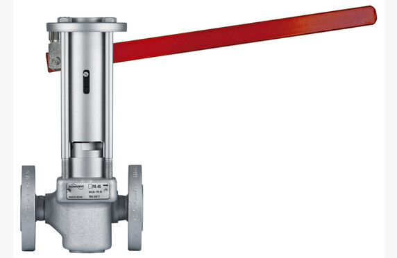
Soft seated ball valves
Soft seated ball valves

Media
Manufacturers
Technical specifications
Sizes: DN 15-500
Pressure Classes: DIN PN 16-160, ANSI 150-2500
Materials: A105 (C22.8), WCB 1304, 316, 316T, Hastelloy B or C, titanium, duplex
Seals: PTFE, RTFE, TGV, AM, Derlin, Devlon
Operating Temperatures: -196 °C…+250 °C
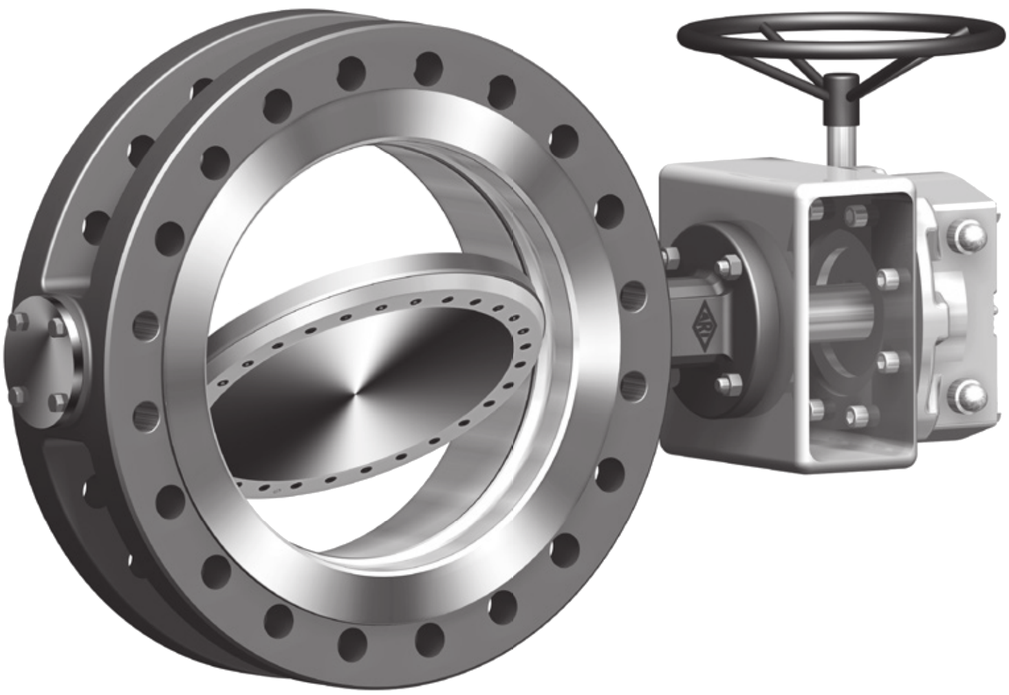
End Connections: between flanges, flanged, threaded, welded
Other: ISO 10497 fire safe
Also Known As: soft seated ball valve
What is a soft seated ball valve?
A soft seal typically refers to PTFE composite seals, with which ball valves are suitable for applications where the temperature does not rise very high (max. 220 °C).
Choosing a Soft Seated Ball Valve
We assist in sizing and selecting the appropriate ball valve for your application.
Our product range includes both two-way and three-way valves. Three-way ball valves are also suitable for distribution applications. There are several sealing options available, for example PTFE, RTFE, TGV, AM, DEVLON, etc.
Our range of three-way valves features both L-ball and T-ball designs for 90° rotating valves. Additionally, the L-ball valves offer a “full bore transflow” option for 120° rotating valves when handling a more viscous medium.
Ball valves are available in one-piece, two-piece, and three-piece constructions. Among these, the two-piece and three-piece models are easier to service.
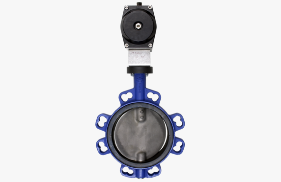
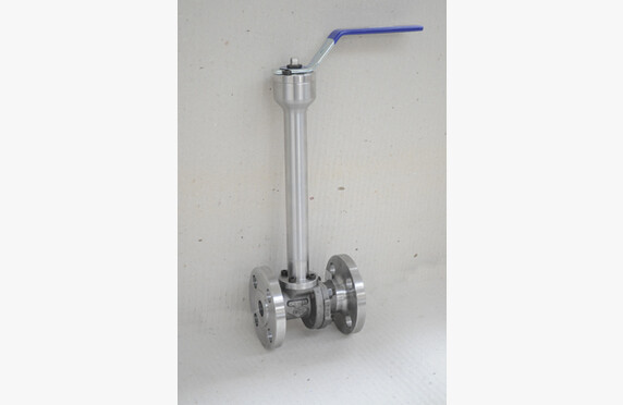
Connection options include welding ends, threaded, or flanged. There is also an alternative – the slim ALFA 10 model which is only the length of the ball. It is a lightweight and cost-effective choice for many applications that require a flanged model but allow for a shorter construction length.
Since the ball valve is a typical process valve, it also has a wide range of materials available. Various combinations of body, ball, and seal materials ensure that a suitable model can be found for different media.
Our range includes valves in accordance with both DIN and ASME classifications.
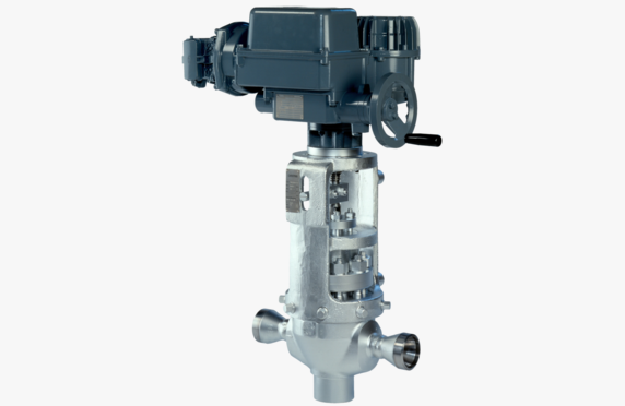
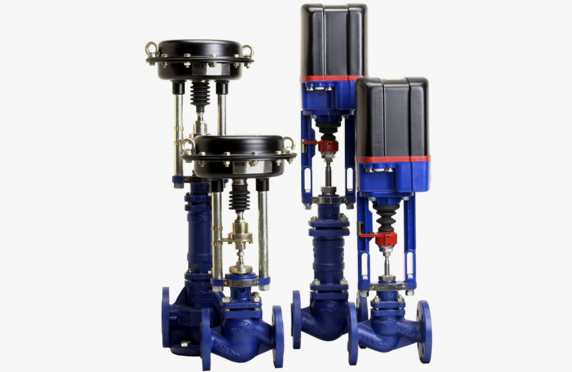
Our ball valves are available with accessories required for manual, pneumatic, or electric actuators.
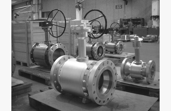
For steam, condensate and process media
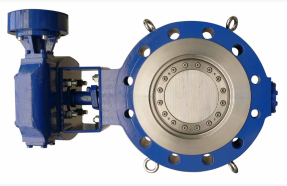
The smaller sizes of ball valves are of a floating design, and the larger ones are trunnion-mounted. They feature a Fire Safe construction, antistatic properties according to BS 5146, and comply with the TA-Luft TüV standards.
We can also supply heating jackets, extension stems, and special sealing solutions (TI, V).
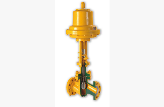
For liquid fuels
In the gas and fuel sectors, a Fire Safe construction is generally required for valves.
For example, in the case of ALFA Valvole, the Fire Safe EN ISO 10497 – API607 V test requirements are observed.
Antistatic properties, on the other hand, comply with BS 5146 and TA-Luft TÜV standards.
Smaller sizes are generally of a floating design, and larger sizes use a trunnion-mounted ball design. However, in some cases, even for smaller sizes it is necessary to opt for a trunnion design, for example at high flow rates.
Our range includes valves from manufacturers such as ALFA Valvole and OMB Spa.
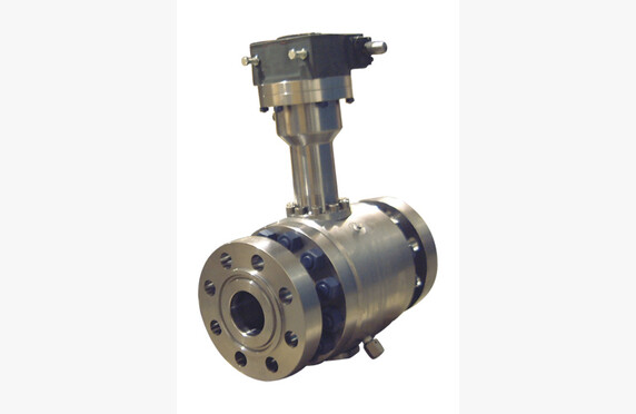
For cryogenic media
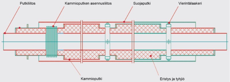
Ball valves intended for cryogenic use differ from conventional ball valves in several fundamental ways. In a cryogenic valve, there is an extension stem that ensures the seal of the stem remains at a higher temperature than the medium. Materials have been selected to withstand extreme cold. The finished valve is clean and dry.
Ball valves designed for cryogenic use are equipped with a venting system for the interspace, because the cold liquid remaining in the interspace expands when it vaporizes and would damage the valve without pressure relief. The pressure relief is achieved either through a drilling on the opposite side or via spring-loaded self-relieving seals. Drilling is a traditional and reliable solution that is also suitable for a floating valve and works reliably. The downside of a drilled pressure relief is that the valve can only be tight in one direction. A more advanced solution is to use self-relieving seals. In this case, the seals of the trunnion-mounted ball valve are designed so that when the interspace pressure rises above the pipeline pressure, the seal allows the pressure to be vented.
Our selection of cryogenic ball valves is comprehensive. We represent OMB and PENTA. Through us, soft-seated and metal-seated valves are available in both floating and trunnion-mounted constructions. Body designs include top-entry and side-entry. Valves are available with full bore and reduced bore.
See the cryogenic valve webinar on YouTube from the Konwell Academy channel here.